
Page 169 - Applied Process Design For Chemical And Petrochemical Plants Volume III
P. 169
66131_Ludwig_CH10D 5/30/2001 4:31 PM Page 132
132 Applied Process Design for Chemical and Petrochemical Plants
Figure 10-76. Condensation down-flow in vertical tubes. Note: h cm average value of condensing coefficient between two points; G con-
densate loading, lb/(hr)(ft) w / P, lb/(hr)(lin. ft); w W/N t , lb/(hr)(tube); W condensate, lb/hr; p perimeter, ft per tube. (Used by permis-
sion: Colburn, A. P. Transactions of American Institute of Chemical Engineers, V. 30., ©1934. American Institute of Chemical Engineers. All rights
reserved.)
Condensing Single Pass Up-Flow in Vertical Tubes
This mechanical configuration is not the usual situation
for most vapor condensers; however, it is convenient for spe-
cial arrangements and in particular to mount directly above
a boiling vessel for refluxing vapors. It can also be used in
special designs to take very hot vapors and generate steam;
however, for all cases a very real limitation must be recog-
nized.
29
Clements and Colver developed the modified Nusselt
equation to correlate hydrocarbon and hydrocarbon mix-
tures in turbulent film condensation:
3
h x x x g l 0.75
Nu x 1.88 10 8 c d (10-110)
k l l k l T
with an average deviation of date of 35.7%,
where
x distance film has fallen
g gravitational constant
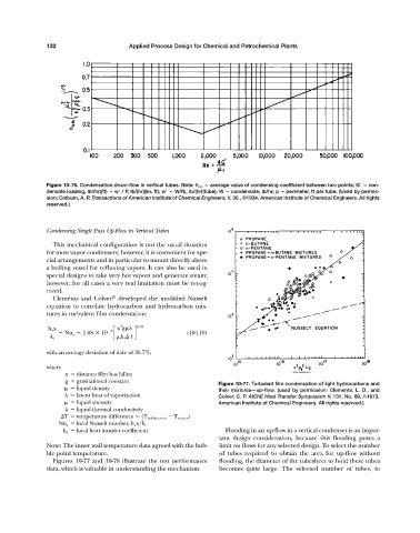
Figure 10-77. Turbulent film condensation of light hydrocarbons and
l liquid density their mixtures—up-flow. (used by permission: Clements, L. D., and
latent heat of vaporization Colver, C. P. AIChE Heat Transfer Symposium V. 131, No. 69, ©1973.
liquid viscosity American Institute of Chemical Engineers. All rights reserved.)
k liquid thermal conductivity
T temperature difference (T bubble point T surface )
Nu x local Nusselt number, h x x/k l
h x local heat transfer coefficient Flooding in an up-flow in a vertical condenser is an impor-
tant design consideration, because this flooding poses a
Note: The inner wall temperature data agreed with the bub- limit on flows for any selected design. To select the number
ble point temperature. of tubes required to obtain the area for up-flow without
Figures 10-77 and 10-78 illustrate the test performance flooding, the diameter of the tubesheet to hold these tubes
data, which is valuable in understanding the mechanism. becomes quite large. The selected number of tubes, to