
Page 170 - Applied Process Design For Chemical And Petrochemical Plants Volume III
P. 170
66131_Ludwig_CH10D 5/30/2001 4:31 PM Page 133
Heat Transfer 133
According to this investigation, the allowable gas rate at
flooding can be increased by having the outlet tube ends
extend through the bottom tubesheet and be cut off at an
angle to the horizontal, rather than just a “square” cut-off.
The angle measured from the horizontal for a vertical tube
is as follows:
Angle % Increase* in Maximum Allowable Gas Rate
30° 05
60° 25
75° 54
*Increase compared to square end tubes 0°
35
The studies of Diehl and Koppany further examined ver-
tical up-flow limitations.
The critical diameter above which the flooding velocity is
independent of diameter is given by:
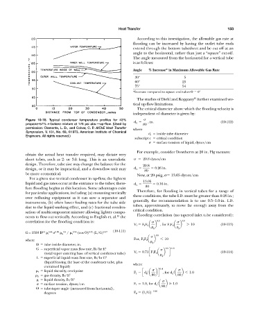
Figure 10-78. Typical condenser temperature profiles for 43% d ic , in. (10-112)
propane–57% n-butane mixture at 176 psi abs.—up-flow. (Used by 80
permission: Clements, L. D., and Colver, C. P. AIChE Heat Transfer where
Symposium, V. 131, No. 69, ©1973. American Institute of Chemical d i inside tube diameter
Engineers. All rights reserved.)
subscript c critical condition
surface tension of liquid, dynes/cm
For example, consider Dowtherm at 20 in. Hg vacuum:
obtain the actual heat transfer required, may dictate very
short tubes, such as 2- or 3-ft long. This is an unrealistic 20.8 dynes>cm
design. Therefore, tube size may change the balance for the 20.8
design, or it may be impractical, and a down-flow unit may d ic 0.26 in.
80
be more economical.
Now, at 20 psig, 13.05 dynes/cm
For a given size vertical condenser in up-flow, the lightest
13.05
liquid and gas rates occur at the entrance to the tubes; there- d ic 0.16 in.
fore flooding begins at this location. Some advantages exist 80
Therefore, for flooding in vertical tubes for a range of
for particular applications, including (a) mounting vertically
these conditions, the tube I.D. must be greater than 0.26 in.;
over refluxing equipment as it can save a separator and
generally, the recommendation is to use 0.5—1.0-in. I.D.
instruments, (b) often lower fouling rates for the tube side
tubes, approximately, to move far enough away from the
due to the liquid washing effect, and (c) fractional conden-
critical condition.
sation of multicomponent mixture allowing lighter compo-
42
nents to flow out vertically. According to English et. al. the Flooding correlation (no tapered inlet tube considered):
correlation for the flooding condition is: 0.5 0.5
V f F 1 F 2 a b , for F 1 F 2 a b 7 10 (10-113)
g g
0.3 0.46 0.09 0.5 0.14 0.32 0.07 (10-111)
G = 1550 D l G / l (cos ) (L/G)
0.5
where For, F 1 F 2 a b 6 10
g
D tube inside diameter, in.
G superficial vapor mass flow rate, lb/hr ft 2 0.5 1.15
V f 0.71cF 1 F 2 a b d (10-114)
(total vapor entering base of vertical condenser tube)
g
L superficial liquid mass flow rate, lb/hr ft 2
(liquid leaving the base of the condenser tube, plus
where
entrained liquid)
0.4
l liquid viscosity, centipoise
F 1 cd i >a bd , for d i >a b 6 1.0
G gas density, lb/ft 3 80 80
l liquid density, lb/ft 3
surface tension, dynes/cm F 1 1.0, for d i >a b 1.0
80
tube-taper angle (measured from horizontal),
degrees F 2 1L>G2 0.25