
Page 166 - Applied Process Design For Chemical And Petrochemical Plants Volume III
P. 166
66131_Ludwig_CH10D 5/30/2001 4:31 PM Page 129
Heat Transfer 129
2770 some of the improved features claimed for heat transfer and
3
ft >sec 0.8 cfs
3600 pressure drop.
The specific features of this new type of shell-side con-
Velocity in 3-in. pipe:
struction provide improved resistance to destructive tube
0.80
15.6 ft>sec vibration compared to the usual plate baffle designs. These
0.0513
units have been applied in practically all of the usual process
This is satisfactory, although a 2-in. nozzle would have a
heat exchanger services including externally finned tubes.
velocity of 34.3 ft/sec. Because this condenser has entering
These units have been fabricated in large shell diameters.
vapors at the dew point, entrainment of some particles is 169
Technical references include Gentry; Gentry, Young, and
always a real possibility; therefore, a low inlet velocity is pre- 170 171
Small; and Gentry and Small.
ferred. Also, overhead vapor lines should have low pressure
drop for vapor at its dew point and a 3-in. line might be indi-
cated when this line is checked.
Condensation Inside Tubes
®
RODbaffled (Shell-Side) Exchangers 70, 82, 94
Horizontal Tube Bundles
(See Figures 10-20A, 10-20-B, 10-20-C, and 10-20-D.) Kern’s 70, 94A modification of the Nusselt development is
The design techniques of this system of baffling are not considered useful.
adequately published in literature, because they are propri-
3
3
etary information of Phillips Petroleum Co. and are licensed 3Lk l l 1 l v 2g4 1>3 3k l l 1 l v 2g4 1>4
h c 0.761 0.612
to design firms for specifically designing the units to ensure 3W T l 4 3 l D i t4
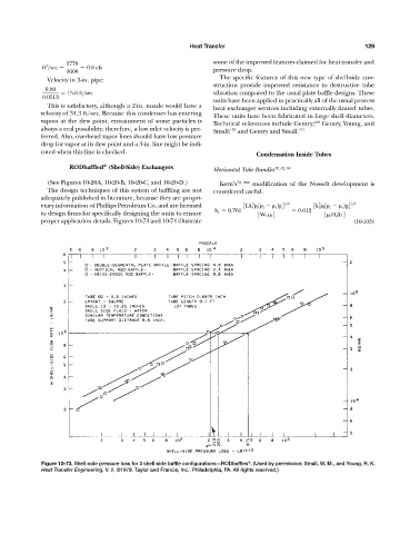
proper application details. Figures 10-73 and 10-74 illustrate (10-103)
Figure 10-73. Shell-side pressure loss for 3 shell-side baffle configurations—RODbaffles . (Used by permission: Small, W. M., and Young, R. K.
®
Heat Transfer Engineering, V. 2, ©1979. Taylor and Francis, Inc., Philadelphia, PA. All rights reserved.)