
Page 167 - Applied Process Design For Chemical And Petrochemical Plants Volume III
P. 167
66131_Ludwig_CH10D 5/30/2001 4:31 PM Page 130
130 Applied Process Design for Chemical and Petrochemical Plants
2 1>3 1>3
31 f 24 314G–24
h c 1.51 (10-105)
3 2
31k f f g24 3 f 4
where
N t number of effective tubes for condensation
L tube length, ft
W condensate flow rate, lb/hr
Other symbols as listed previously.
Subscript:
f liquid film
These relations are good for single-pass tube side units;
however, for multipass units, the number of available vapor
tubes must be determined at the end of the first and each suc-
ceeding pass, as the lower liquid carrying tubes must not be
considered as available tubes. Thus, G should be evaluated
for each pass, and the individuals evaluated separately, or an
average determined as the average of the pass average values
of h cm .
Condensing Inside Horizontal Tubes
1
The correlation of Akers, et. al., has given good results in
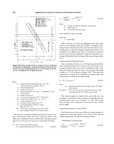
Figure 10-74. Ratio of heat transfer to pressure loss for 3 shell-side some industrial designs. The authors report that some verti-
configurations—RODbaffles . (Used by permission: Small, W. M., and
®
Young, R. K. Heat Transfer Engineering, V. 2, ©1979. Taylor and Fran- cal and inclined tube data is also correlated on the same
cis, Inc., Philadelphia, PA. All rights reserved.) basis. The sharp break in the data occurs around a Reynolds
4
number of 5 10 as shown in Figure 10-75. The mass flow
rate used to correlate is the arithmetic average of inlet and
outlet liquid condensate and vapor flows:
– –
G e = G L + G g ( L / g ) 1/2 (10-106)
where
2
k l liquid thermal conductivity, Btu/(hr) (ft ) where
(unit temperature gradient, °F/ft) G e equivalent mass flow inside tubes, lb/hr (ft of flow
2
l liquid density, lb/ft 3 cross section)
–
–
v vapor density, lb/ft 3 G L and G g arithmetic averages of condensate and vapor flow
l liquid viscosity, lb/(hr) (ft), [ centipoise 2.42 respectively, lb/hr (ft of flow cross section)
2
lb/(hr) (ft)]
D i inside diameter, ft The relation applies to systems that potentially are con-
8
g acceleration of gravity, 4.18 10 ft/(hr) 2
densable as contrasted to those systems containing noncon-
t temperature difference (t sv t s ) °F
densable gases such as air, nitrogen, etc. All of the vapor
t s surface temperature, °F
does not have to be condensed in the unit for the correla-
t sv saturated vapor temperature, °F
h c condensing film coefficient, mean, tion to apply.
2
Btu/(hr) (ft ) (°F)
W T total vapor condensed in one tube, lb/hr Subcooling Condensate in Vertical Tubes
L tube length, ft (effective for heat transfer)
The total unit size is the sum of the area requirements for
Because the condensate builds up along the bottom por- condensation plus subcooling of the liquid to the desired
tion of horizontal tubes, the layer builds up thicker and outlet temperature. For the subcooling portion:
70
offers more resistance to heat transfer. Kern proposes good
82
agreement with practical experience using the following 1. McAdams recommends:
c 1>3 4W 1>3
h cm
G W/(0.5 LN t ), special G loading 0.01a b a b (10-107)
3 2
for a single horizontal tube, lb/(hr) (ft) (10-104) 2k f f g> f 2 k f D i