
Page 168 - Applied Process Design For Chemical And Petrochemical Plants Volume III
P. 168
66131_Ludwig_CH10D 5/30/2001 4:31 PM Page 131
Heat Transfer 131
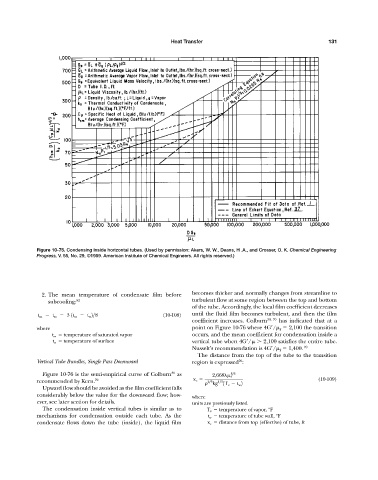
Figure 10-75. Condensing inside horizontal tubes. (Used by permission: Akers, W. W., Deans, H .A., and Crosser, O. K. Chemical Engineering
Progress, V. 55, No. 29, ©1959. American Institute of Chemical Engineers. All rights reserved.)
2. The mean temperature of condensate film before becomes thicker and normally changes from streamline to
subcooling: 82 turbulent flow at some region between the top and bottom
of the tube. Accordingly, the local film coefficient decreases
t m t sv 3 1t sv t w 2>8 (10-108) until the fluid film becomes turbulent, and then the film
coefficient increases. Colburn 30, 70 has indicated that at a
where point on Figure 10-76 where 4G / f 2,100 the transition
t sv temperature of saturated vapor occurs, and the mean coefficient for condensation inside a
t w temperature of surface vertical tube when 4G / 2,100 satisfies the entire tube.
Nusselt’s recommendation is 4G / f 1,400. 70
The distance from the top of the tube to the transition
70
Vertical Tube Bundles, Single Pass Downward region is expressed :
30
Figure 10-76 is the semi-empirical curve of Colburn as 2,668 f 5>3
recommended by Kern. 70 x c 2>3 1>3 (10-109)
kg 1T v t w 2
Upward flow should be avoided as the film coefficient falls
considerably below the value for the downward flow; how- where
ever, see later section for details. units are previously listed
The condensation inside vertical tubes is similar as to T v temperature of vapor, °F
mechanisms for condensation outside each tube. As the t w temperature of tube wall, °F
condensate flows down the tube (inside), the liquid film x c distance from top (effective) of tube, ft