Page 239 - Applied Process Design For Chemical And Petrochemical Plants Volume III
P. 239

66131_Ludwig_CH10G  5/30/2001 4:37 PM  Page 202


                       202                       Applied Process Design for Chemical and Petrochemical Plants


                                  1,500177.82                                valve; the vapor outlet assumes short pipe connection, a 90°
                       Clean: U c             74.0                           welded ell and a fully open gate valve. Reference 73 dis-
                                  77.8 	 1,500
                                                                             cusses exchanger piping layout.
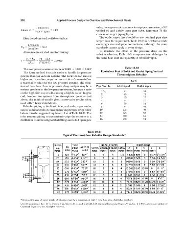
                         Dirty based on total available surface:               The outlet vapor line should be two nominal pipe sizes
                                                                             larger than the liquid inlet. Table 10-33 is helpful to relate
                                                                             exchanger size and pipe connections, although the same
                            1,528,600
                       U D            56.3                                   standards cannot apply to every design.
                            145121602
                                                                               To illustrate the effect of the pressure drop on the
                         Allowance in selected unit for fouling:
                                                                             reboiler selection, Table 10-34 compares several designs for
                                                                             the same heat load and quantity of reboiled vapor.
                           U c   U D  74   56.3
                       r                       0.00425
                                    1742156.32
                            U c U D
                                                                                                 Table 10-32
                         This compares to assumed value of 0.001 	 0.001   0.002
                                                                                Equivalent Feet of Inlet and Outlet Piping Vertical
                         The Kern method is usually easier to handle for pressure
                                                                                            Thermosiphon Reboiler
                       systems than for vacuum systems. The recirculation ratio is
                       higher and, therefore, requires more trials to “narrow-in” on
                                                                                                     Eq ft
                       a reasonable value for the low pressure systems. The omis-
                       sion of two-phase flow in pressure drop analysis may be a  Pipe Size, In.  Inlet Liquid  Outlet Vapor
                       serious problem in the low pressure system, because a ratio
                                                                                  1             21            10
                                                                                1  / 2
                       on the high side may result, causing a high h i value. In gen-
                                                                                2               25            12
                       eral, however, for systems from atmospheric pressure and
                                                                                3               35            17
                       above, the method usually gives conservative results when  4             44            21
                       used within Kern’s limitations.                          6               65            32
                         Reboiler piping at the liquid inlet and at the vapor outlet  8         84            40
                       can be summarized for convenience in pressure drop calcu-  10            103           49
                       lations into the suggested equivalent feet of Table 10-32. The  12       123           58
                       inlet assumes piping to conveniently pipe the reboiler to a  14          140           65
                       distillation column using welded fittings and a full open gate  16       159           74


                                                                       Table 10-33
                                                     Typical Thermosiphon Reboiler Design Standards*


                       *Cross-section area of vapor nozzle off channel must be a minimum of 1.25   total flow area of all tubes (author).
                       Used by permission: Lee, D. C., Dorsey, J. W., Moore, G. Z., and Mayfield, F. D. Chemical Engineering Progress, V. 52, No. 4, ©1956. American Institute of
                       Chemical Engineers, Inc. All rights reserved.
   234   235   236   237   238   239   240   241   242   243   244