
Page 240 - Applied Process Design For Chemical And Petrochemical Plants Volume III
P. 240
66131_Ludwig_CH10G 5/30/2001 4:37 PM Page 203
Heat Transfer 203
Table 10-34
Vertical Thermosiphon Reboiler Comparison: Effect
of Pressure Drop and Pipe Size on Selection
3 / 4 In. 1 In. 1 In. 1 In.
4 Ft 6 Ft 6 Ft 6 Ft
Tubes: Long Long Long Long
No. tubes 143 50 66 66
Inlet pipe size, in. 6 6 4 6
Outlet pipe size, in. 8 8 6 8
Shell I.D., in. 15.25 12 13.25 13.25
Recirc. ratio 42 40.5 42.1 55.7
P tubes, psi 0.97 1.55 1.03 1.31
P inlet pipe, psi 0.084 0.0789 0.41 0.137
P outlet pipe, psi 0.085 0.0824 0.251 0.111
P expansion, psi 0.00097 0.00209 0.00118 0.0011
U (calc.) 79.3 92.6 82.4 94.0
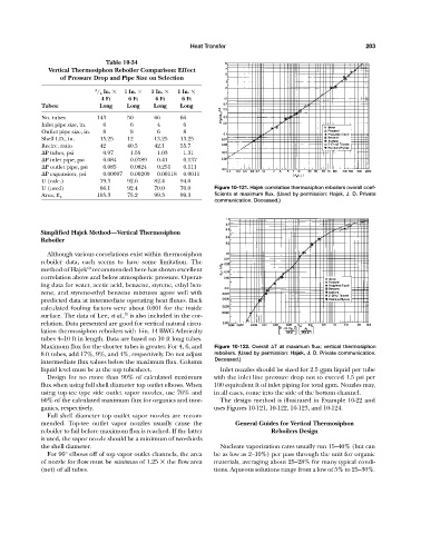
U (used) 66.1 92.4 70.0 70.0 Figure 10-121. Hajek correlation thermosiphon reboilers overall coef-
105.3 75.2 99.3 99.3 ficients at maximum flux. (Used by permission: Hajek, J. D. Private
Area, ft 2
communication. Deceased.)
Simplified Hajek Method—Vertical Thermosiphon
Reboiler
Although various correlations exist within thermosiphon
reboiler data, each seems to have some limitation. The
60
method of Hajek recommended here has shown excellent
correlation above and below atmospheric pressure. Operat-
ing data for water, acetic acid, benzene, styrene, ethyl ben-
zene, and styrene-ethyl benzene mixtures agree well with
predicted data at intermediate operating heat fluxes. Back
calculated fouling factors were about 0.001 for the inside
75
surface. The data of Lee, et al., is also included in the cor-
relation. Data presented are good for vertical natural circu-
lation thermosiphon reboilers with 1-in. 14 BWG Admiralty
tubes 4–10 ft in length. Data are based on 10 ft long tubes.
Maximum flux for the shorter tubes is greater. For 4, 6, and Figure 10-122. Overall T at maximum flux; vertical thermosiphon
8 ft tubes, add 17%, 9%, and 4%, respectively. Do not adjust reboilers. (Used by permission: Hajek, J. D. Private communication.
intermediate flux values below the maximum flux. Column Deceased.)
liquid level must be at the top tubesheet. Inlet nozzles should be sized for 2.5 gpm liquid per tube
Design for no more than 90% of calculated maximum with the inlet line pressure drop not to exceed 1.5 psi per
flux when using full shell diameter top outlet elbows. When 100 equivalent ft of inlet piping for total gpm. Nozzles may,
using top-tee type side outlet vapor nozzles, use 76% and in all cases, come into the side of the bottom channel.
60% of the calculated maximum flux for organics and inor- The design method is illustrated in Example 10-22 and
ganics, respectively. uses Figures 10-121, 10-122, 10-123, and 10-124.
Full shell diameter top outlet vapor nozzles are recom-
mended. Top-tee outlet vapor nozzles usually cause the General Guides for Vertical Thermosiphon
reboiler to fail before maximum flux is reached. If the latter Reboilers Design
is used, the vapor nozzle should be a minimum of two-thirds
the shell diameter. Nucleate vaporization rates usually run 15–40% (but can
For 90° elbows off of top vapor outlet channels, the area be as low as 2–10%) per pass through the unit for organic
of nozzle for flow must be minimum of 1.25 the flow area materials, averaging about 25–28% for many typical condi-
(net) of all tubes. tions. Aqueous solutions range from a low of 5% to 25–30%.