
Page 245 - Applied Process Design For Chemical And Petrochemical Plants Volume III
P. 245
66131_Ludwig_CH10G 5/30/2001 4:38 PM Page 208
208 Applied Process Design for Chemical and Petrochemical Plants
Horizontal Tubes: Boiling Outside, Submerged 14
Conditions: Pressure to 500 psi, temperatures of satu-
rated liquid to 700°F
Tubes: 0.025–0.75-in. O.D. (data of correlation)
Fluids: Hydrocarbons, alcohols, benzene, chlori-
nated compounds, low-temperature nit-
rogen, and oxygen
3
1 k v 1 L v 2g ¿ 1>4
h¿ a a¿ a 36.5bc d (10-203)
d o t b
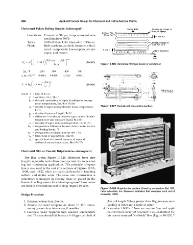
Figure 10-126. Horizontal film type cooler or condenser.
t b , °F 200 300 400 500
a, in./(ft) 1/4 0.0461 0.0450 0.0445 0.0441
2
c p t b
¿ h fg a1 0.4 b (10-204)
¿
where d tube O.D., in.
a constant, (in.)/(ft) 1/4
k a thermal conductivity of vapor at arithmetic average
mean temperature, Btu/hr (°F)(ft)
v density of vapor at its arithmetic mean temperature, Figure 10-127. Typical cast iron cooling section.
lb/ft 3
L density of saturated liquid, lb/ft 3
difference in enthalpy between vapor at its arithmetic
temperature and saturated liquid, Btu/lb
viscosity of vapor at mean temperature, lb/hr (ft)
t b temperature difference between heat transfer surface
and boiling liquid, °F
2
h a average film coefficient Btu/hr (ft ) (°F)
h fg latent heat of vaporization, Btu/lb
c p specific heat at constant pressure of vapor at
arithmetic mean temperature, Btu/lb (°F)
Horizontal Film or Cascade Drip-Coolers—Atmospheric
The film cooler, Figure 10-126, fabricated from pipe
lengths, is popular and relatively inexpensive for some cool-
ing and condensing applications. The principle of opera-
tion is also used in the cast iron sections of Figures 10-5A,
10-5B, and 10-127, which are particularly useful in handling
sulfuric and similar acids. The same unit construction is
sometimes submerged in cooling tanks or placed in the
basins of cooling towers. Graphite-impregnated film coolers
are used in hydrochloric acid cooling (Figure 10-128).
Figure 10-128. Graphite film coolers. (Used by permission: Bul. 537,
Falls Industries, Inc. Research indicates that company went out of
Design Procedure business, 1999.)
1. Determine heat duty, Btu/hr. plan coil length. Values greater than 10 gpm cause over-
2. Assume exit water temperature about 10–15°F (maxi- flooding of tubes and a waste of water.
mum) greater than inlet water, if possible. 4. Determine LMTD if flows are counterflow and apply
8
3. Calculate water required with selected temperature the correction factor of Bowman et al., established for
rise. This rate should fall between 2–10 gpm per lin ft of this type of unmixed “shell-side” flow (Figure 10-129). 70