Page 246 - Applied Process Design For Chemical And Petrochemical Plants Volume III
P. 246

66131_Ludwig_CH10G  5/30/2001 4:38 PM  Page 209


                                                                    Heat Transfer                                          209

                                                                                               Table 10-35
                                                                              Typical Fouling Factors—Cast Iron Cooling Sections

                                                                                                      Inside    Outside
                                                                           Service                   Fouling    Fouling
                                                                           Concentrated sulfuric acid  0.002       —
                                                                           Ammonia liquor             0.002        —
                                                                           Clean water                0.001      0.005
                                                                           Clean oil                  0.002        —
                                                                           Dirty oil                  0.005        —
                                                                           Tar                        0.010        —
                                                                           Dirty water                            0.01
                                                                           Sea water, brackish water            0.01—0.05
                                                                           Used by permission: Cat. HT-23, National U.S. Radiator Corp. Existence
                                                                           of company not confirmed (1998). Value for sea water provided by this
                                                                           author.


                                                                                               Table 10-36
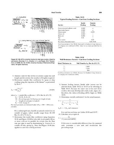
                     Figure 10-129. MTD correction factors for drip type coolers. (Used by  Wall Resistance Factors—Cast Iron Cooling Sections
                     permission: Bowman, R. A., Mueller, A. C., and Nagle, W.M. Transac-
                     tions of ASME, No. 62, ©1940. American Society of Mechanical Engi-  Metal Thickness, in.  Wall Transfer, h w , Btu/hr (ft )(°F)
                                                                                                                       2
                     neers. All rights reserved.)
                                                                                 1                         1,800
                                                                                  / 4
                                                                                 3                         1,350
                                                                                  / 8
                                                                                 1                           900
                                                                                  / 2
                                                                           Used by permission: Cat. HT-23, National U.S. Radiator Corp. Existence
                                                                           of company not confirmed (1998).
                       5. Assume a unit for the service or assume a pipe size and
                         length and determine the number of lengths required.
                       6. Determine outside film coefficient for spray or drip
                                                           81
                         cooling using the equation of McAdams as presented
                         by Kern. 70                                         8. Assume fouling factors. Inside tube factors can be
                                                                               selected from Table 10-12 or 10-13 or by referring to
                                 1>3
                             G d                                               Table 10-15. Because the water rate is low over these
                      h o   65a  b                               (10-205)
                             D o                                               coolers, they may develop salt crusts, scale, algae, etc.;
                                                                               therefore, the values of fouling will be high, see Table
                                                               2
                     where h o   outside film coefficient,   25%, Btu/hr (ft )(°F)  10-35.
                          G d   W/2L, lb/hr (ft)                             9. Determine overall coefficient U in the usual manner.
                          W   lb cooling water/hr flowing over length of tube            1
                           L   length of each pipe in bank, ft              U
                                                                                1        1       1
                          D o   O.D. of pipe, ft                                  	 r i 	  	 r o
                     For most purposes, an estimated value of h o   500   550 is con-  h io  h w  h o
                     servative.
                                                                            L w >k     1>h w , wall resistance
                         For a submerged unit, handle as natural convection on
                                                                               For cast iron sections, see Tables 10-36 and 10-37.
                         outside of pipes; values usually range from 40–130
                                                                            10. Calculate area required:
                         Btu/hr (ft )(°F) for h o .
                                  2
                       7. Determine the inside film coefficient using Equation         Q
                                                                            A
                         10-41 and Figure 10-46 for tube-side heat transfer. If two  U 1corrected LMTD2
                         or more coils are in parallel, be certain that the flow
                         rate per pipe is used in determining h i . Correct h i to  If this area is considerably different than the assumed
                         outside of tube, giving h io . Note that Figure 10-46 also  unit, reassume a new unit and recalculate the
                         applies to cast iron cooling sections.                preceding steps.
   241   242   243   244   245   246   247   248   249   250   251