
Page 248 - Applied Process Design For Chemical And Petrochemical Plants Volume III
P. 248
66131_Ludwig_CH10G 5/30/2001 4:38 PM Page 211
Heat Transfer 211
Divide this f by 144 in order to use in p t Equation10-191
or 10-207.
Stoever 108, 109 presents convenient tables for pressure drop
evaluation.
Pressure drop through the return ends of exchangers for
any fluid is given as four velocity heads per tube pass 70
4nv 2
, ft
2g¿
2
4nv s 62.5
p r a b, psi (10-212)
12g¿2 144
This is given in Figure 10-139.
where p r return end pressure loss, including entrance
losses, psi
n no. of tubes passes per exchanger
g acceleration of gravity, 32.2 ft/(sec) 2
s specific gravity of fluid (vapor or liquid) referred
to water
v tube velocity, ft/sec
2
4n1G–2 1
pr a b
2g¿s 162.5211442
G mass velocity for tube side flow,
2
lb/(sec) (ft cross-section of tube)
Total Tube Side Pressure Drop
p t p r , psi (10-213)
Tube Side Condensation Pressure Drop
70
Kern recommends the following conservative relation:
2
9.561102 12 f1G t 2 Ln
p t , psi (10-214)
D i s
This is one-half the values calculated for straight fluid
drop, based on inlet flows; f is from Figure 10-137.
B. Shell Side
Pressure losses through the shell side of exchangers are
subject to much more uncertainty in evaluation than for
tube side. In many instances, they should be considered as
approximations or orders of magnitude. This is especially
true for units operating under vacuum less than 7 psia.
Very little data has been published to test the above-atmos-
pheric pressure correlations at below-atmospheric pres-
sures. The losses due to differences in construction, baffle
clearances, tube clearances, etc., create indeterminate val-
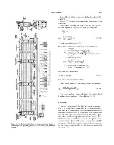
Figure 10-131. Typical sectional cooler using assembly of standard-
ized components. (Used by permission: SGL Technic, Inc., Karbate ® ues for exact correlation. Also see the short-cut method of
Division.) reference 279.