
Page 252 - Applied Process Design For Chemical And Petrochemical Plants Volume III
P. 252
66131_Ludwig_CH10G 5/30/2001 4:38 PM Page 215
Heat Transfer 215
2
4nv s 62.5 where f s friction factor from Figure 10-140, for plain bare
p r a b, psi tubes, f s f/1.2 (from Figure 10-140), shell side
2g¿ 144 2
G s mass velocity, lb/hr (ft of flow area)
D e equivalent diameter of tubes, ft. See Figure 10-54 or
Table 10-21.
D s I.D. of shell, ft
N c number of baffles
(N c 1) number of times fluid crosses bundle from inlet to
outlet
g 4.17 10 8
s specific gravity of gas or liquid referenced to water
s (
/
w ) 0.14 , subscript w refers to wall condition
viscosity, lb/hr (ft) (centipoise) (2.42)
For values of specific gravity for noncondensing gases and
vapors use the average density at inlet and outlet conditions
referenced to water at 62.4 lb/ft .
3
Alternate: Segmental Baffles Pressure Drop
(10-220)
p s p b p c
a. Baffle Window Pressure Drop, p b , psi
This drop is usually very small unless the baffle cut has
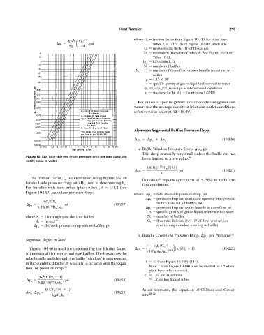
Figure 10-139. Tube side end return pressure drop per tube pass; vis- been limited to a low value. 36
cosity close to water.
2
2.91102 13 1G b 2 1N c 2
p b , psi (10-221)
s
The friction factor, f s , is determined using Figure 10-140 36
Donohue reports agreement of 36% in turbulent
for shell-side pressure drop with D e , used in determining R e .
flow conditions.
For bundles with bare tubes (plain tubes), f s f/1.2 (see
Figure 10-140), calculate pressure drop:
where p s total shell-side pressure drop, psi
p b pressure drop across window opening of segmental
2
f s G s LN c baffles, total for all baffles, psi
p s psi (10-217)
10
5.221102 D e ¿s s p c pressure drop across the bundle in cross-flow, psi
s specific gravity of gas or liquid referenced to water
where N c 1 for single-pass shell, no baffles N c number of baffles
2
s (
/
w ) 0.14 G b flow rate, lb fluid/(hr) (ft of flow cross-section
p s shell side pressure drop with no baffles, psi area through window opening in baffle)
b. Bundle Cross-flow Pressure Drop, p c , psi, Williams 126
Segmental Baffles in Shell
c b f f 1G c 2 2
Figure 10-140 is used for determining the friction factor p c a 9 0.14 b1n c 21N c 12 (10-222)
10 g 1
>
w 2
(dimensional) for segmental type baffles. The loss across the
tube bundle and through the baffle “window” is represented
in the combined factor, f, which is to be used with the equa- f f (f, from Figure 10-140) (144)
Note: f from Figure 10-140 must be divided by 1.2 when
tion for pressure drop. 70
plain bare tubes are used.
2
f s G s D s ¿1N c 12 c b 1.07 for bare tubes
p s , psi (10-218) 1.2 for low finned tubes
10
5.221102 D e s s
2
f s G s D s ¿1N c 12 As an alternate, the equation of Chilton and Gener-
also, p s (10-219) 28, 82
2g D e s aux: