
Page 251 - Applied Process Design For Chemical And Petrochemical Plants Volume III
P. 251
66131_Ludwig_CH10G 5/30/2001 4:38 PM Page 214
214 Applied Process Design for Chemical and Petrochemical Plants
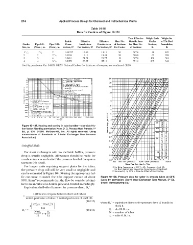
Table 10-38
Data for Coolers of Figure 10-131
Total Effective Weight Each Weight Set
Inside Effective Effective Max. No. Outside Area Cooler of Tie Rod
Cooler Pipe I.D. Pipe O.D. Cross- Inside Area Outside Area of Sections for Max. No. Section, Assemblies,
Size, in. (Nom.), in. (Nom.), in. section, ft 2 Per Section, ft 2 Per Section, ft 2 Per Cooler of Sections lb lb
1 1 2 00.01227 10.60 14.14 26 367.6 040 182
1 / 2 1 / 2
3
2 2 2 / 4 0.0218 14.14 19.44 20 388.8 065 299
3 3 4 0.0491 21.21 28.27 13 367.6 180 381
1
4 4 5 / 4 0.0873 28.27 37.11 10 371.1 285 541
Used by permission: Cat. S-6820, ©1953. National Carbon Co. Existence of company not confirmed (1998).
Figure 10-137. Heating and cooling in tube bundles—tube-side fric-
tion factor. (Used by permission: Kern, D. Q. Process Heat Transfer, 1 st
Ed., p. 836, ©1950. McGraw-Hill, Inc. All rights reserved. Using
nomenclature of Standards of Tubular Exchanger Manufacturers
Association.)
Unbaffled Shells
For short exchangers with no shell-side baffles, pressure
drop is usually negligible. Allowances should be made for
nozzle entrances and exits if the pressure level of the system
warrants this detail.
For longer units requiring support plates for the tubes,
the pressure drop will still be very small or negligible and
can be estimated by Figure 10-140 using the appropriate baf-
fle cut curve to match the tube support cut-out of about Figure 10-138. Pressure drop for water in smooth tubes at 68°F.
rd
70
50%. Kern recommends that the flow be considered simi- (Used by permission: Scovill Heat Exchanger Tube Manual, 3 Ed.
Scovill Manufacturing Co.)
lar to an annulus of a double pipe and treated accordingly.
Equivalent shell-side diameter for pressure drop, D e :
4 1flow area of space between shell and tubes2
wetted perimeter of tubes wetted perimeter of shell I.D.
(10-215)
2
2
D s >4 N d o >4 where D e equivalent diameter for pressure drop of bundle in
4c d shell, ft
144
D e ¿ (10-216) D s shell I.D., in.
N d o D s N number of tubes
12 12 d o tube O.D., in.