
Page 255 - Applied Process Design For Chemical And Petrochemical Plants Volume III
P. 255
66131_Ludwig_CH10G 5/30/2001 4:38 PM Page 217
Heat Transfer 217
2
2
p c 4f s ’’ n c G max >12g’ 2 11442 (10-223) 9.561102 12 1f s 2G s D s ¿1N c 12
p s , psi (10-228)
D e ¿s
For triangular pitch: 57, 58, 82 This equation gives values that are half of those calculated
as total gas flow for the shell side by using friction factors
r t from 1.5 to 4.0
from Figure 10-140. (Note that f s for plain or bare tubes
0.1175 D o G max 1.16 f/1.2 (with f from Figure 10-140)).
f s – c0.25 da b (10-224)
1r t 12 1.08
f ¿ The method of Buthod 22 has given unusually good
checks with data from industrial units. In general this
For square or in-line pitch: 57, 58, 82 method appears to give results that are slightly higher than
field data but not as high as the other methods presented
r t from 1.5 to 4.0 previously. For shell-side pressure drop:
0.15
0.08r 1 D o G max
f s – a0.044 ba b (10-225) p s 1total2 p long. p c (10-229)
1r t 12 a
f ¿
1.13
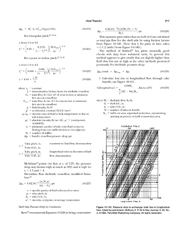
a 0.43 (10-226) 1. Calculate loss due to longitudinal flow through tube
bundle; use Figure 10-141.
r 1
0.04W s 2
where c b constant G1longitudinal2 , lbs>sec 1ft 2 (10-230)
2
f f dimensionless friction factor for shellside cross-flow 1D s Nd o 2B ca
2
G c mass flow, lb/(hr) (ft of cross section at minimum 4
free area in cross-flow)
2
G max mass flow, lb/sec (ft of cross section at minimum where W s shell-side flow, lb/hr
free area in cross-flow) D s shell I.D., in.
fluid density, lb/ft 3 d o tube O.D., in.
g acceleration constant 32.2 ft/(sec) 2 N number of tubes in bundle
/
w viscosity ratio of fluid at bulk temperature to that at B ca baffle cut area, expressed as fraction, representing
wall temperature opening as percent of shell cross-section area.
f absolute viscosity, lb/sec (ft),
t (centipoises)
(0.000672)
n c minimum number of tube rows fluid crosses in
flowing from one baffle window to one adjacent.
N c number of baffles
p c bundle cross-flow pressure drop, psi
Tube pitch, in. transverse to fluid flow, dimensionless
r t
Tube O.D., in.
Tube pitch, in. longitudinal value in direction of fluid
r l
Tube O.D., in. flow, dimensionless
82
McAdams points out that at r t of 1.25, the pressure
drop may deviate high as much as 50% and is high for
r t 1.5 and 4.
Streamline flow shell-side cross-flow; modified Dono-
hue: 38
1n c 2G c
¿
5
p c 3.021102 , psi (10-227)
s1p d o 2
s specific gravity of fluid referenced to water
p tube pitch, in.
d o tube O.D., in.
viscosity, centipoise, at average temperature
Shell Side Pressure Drop in Condensers Figure 10-141. Pressure drop in exchanger shell due to longitudinal
flow. (Used by permission: Buthod, A. P. Oil & Gas Journal, V. 58, No.
70
Kern recommends Equation 10-228 as being conservative: 3, ©1960. PennWell Publishing Company. All rights reserved.)