
Page 257 - Applied Process Design For Chemical And Petrochemical Plants Volume III
P. 257
66131_Ludwig_CH10G 5/30/2001 4:38 PM Page 219
Heat Transfer 219
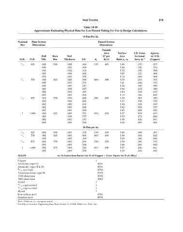
Table 10-39
Approximate Estimating Physical Data for Low-Finned Tubing for Use in Design Calculations
19 Fins Per In.
Nominal Plain Section Finned Section
Size Dimensions Dimensions
Outside
Area Surface I.D. Cross Approx.
Wall Root Wall ft per Area Sectional wt/ft lb
2
O.D. O.D. Thk. Dia. Thickness I.D. d e lin ft Ratio a o /a i Area, in. 2 (Copper)
5 .625 .042 .500 .028 .444 .535 .405 3.48 .155 .275
/ 8
.049 .035 .430 3.60 .145 .316
.058 .042 .416 3.72 .136 .368
.065 .049 .402 3.85 .127 .408
.072 .065 .370 4.18 .108 .444
3 .750 .049 .625 .028 .569 .660 .496 3.33 .254 .344
/ 4
.049 .035 .555 3.41 .242 .376
.058 .042 .541 3.50 .230 .449
.065 .049 .527 3.60 .218 .490
.082 .065 .495 3.84 .192 .612
.095 .083 .459 4.13 .166 .695
7 .875 .054 .750 .035 .680 .785 .588 3.30 .363 .483
/ 8
.058 .042 .666 3.37 .349 .530
.065 .049 .652 3.44 .334 .589
.082 .065 .620 3.62 .302 .727
.095 .083 .584 3.85 .268 .829
1 1.000 .058 .875 .042 .791 .910 .678 3.27 .492 .612
.065 .049 .777 3.33 .474 .680
.082 .065 .745 3.48 .436 .841
.095 .083 .709 3.65 .395 .965
16 Fins per in.
5 .625 .082 .500 .065 .370 .540 .368 3.80 .108 .497
/ 8
3 .750 .082 .625 .065 .495 .665 .438 3.38 .192 .612
/ 4
.095 .083 .459 3.63 .166 .695
7 .875 .082 .750 .065 .620 .790 .520 3.20 .302 .727
/ 8
.095 .083 .584 3.40 .268 .829
1 1.000 .082 .875 .065 .745 .917 .598 3.07 .436 .841
.095 .083 .709 3.22 .395 .965
ALLOY wt/ft Conversion Factor (wt/ft of Copper Conv. Factor wt/ft of Alloy)
Copper 1
Admiralty (type C) .9531
Admiralty (types B & D) .9531
85 / 15 red brass .9780
Aluminum brass (type B) .9319
1100 aluminum .3032
3003 aluminum .3065
Nickel 1
70 / 30 cupro-nickel 1
90 / 10 cupro-nickel 1
Monel 1
Low carbon steel .8761
Stainless steel .8978
Note: Units are in., except as noted.
Used by permission: Engineering Data Book, Section 2, ©1959. Wolverine Tube, Inc.