
Page 262 - Applied Process Design For Chemical And Petrochemical Plants Volume III
P. 262
66131_Ludwig_CH10G 5/30/2001 4:38 PM Page 224
224 Applied Process Design for Chemical and Petrochemical Plants
allowances built in for entrance and exit losses to the shell and
leakage at baffles. 206 The suggested pressure drop for shell-side
heating or cooling, including entrance and exit losses is
2
f G c D s 1n b 12
P s , psi (10-238)
10
15.22 10 21D e s s 2
2
where f friction factor, dimensional, ft / in. 2
P s shell-side pressure drop, psi
2
f friction factor, ft / in. 2
2
G c cross-flow mass velocity, lb/(ft ) (hr)
D s shell I.D., ft
n b number of baffles
D e D es equivalent O.D. of tubes, ft, see earlier discus-
sion on this topic.
d e d es equivalent O.D. of tubes, in., see Figures 10-147
or 10-148 for numerical values.
s specific gravity, dimensionless
P s pressure drop of fluid, heated or cooled, including
entrance and exit losses, lb/in. 2
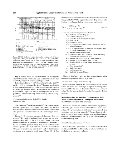
Figure 10-148. Shell-side friction factors for bundles with 20%-cut
segmental baffles, one seal strip per 10 rows of tubes, and TEMA s viscosity correction (
/
w ), dimensionless
clearances. These factors can be used for plain or low-finned tubes
w viscosity of fluid at wall of tube, lb/(ft-hr)
with the appropriate values of D es or d es . (Source: Engineering Data
viscosity of fluid in bulk at caloric temperature,
Book, ©1960. Wolverine Tube, Inc. Used by permission: Kern, D. Q., lb/(ft-hr)
and Kraus, A. D. External Surface Heat Transfer, p. 511, ©1972. fluid density, lb/ft 3
McGraw-Hill Book Co., Inc. All rights reserved.) d s shell diameter, in.
B baffle spacing, in.
Re s shell-side Reynolds Number
Figure 10-147 allows for the correction for the by-pass Note that this figure can be used for plain or low-fin tubes
area between the outer tube limit of the bundle and the when the appropriate value of D e is used. 206
shell I.D., or as an alternative, see Figure 10-54.
Tube-Side Heat Transfer and Pressure Drop
Referring to Figure 10-147, the marking “low-fin limit” 206
at Re 500 is explained by Kern; 206 because the low-fin Because finned tubes of the low-fin design are standard
tube is somewhat more inclined to insulating itself with liq- tubes, the inside heat exchange and pressure drop perfor-
uids of high viscosity, when a low shell-side Re number is mance will be the same as determined for “plain” or “bare”
the result of a high mass velocity and high viscosity as com- tubes. Use the appropriate information from earlier design
pared to a low mass velocity at low viscosity, caution is sug- sections.
gested. 206
Design Procedure for Shell-Side Condensers and Shell-
Pressure Drop in Exchanger Shells Using Bundles Side Condensation with Gas Cooling of Condensables,
of Low-Fin Tubes Fluid-Fluid Convection Heat Exchange
The Delaware 207 work is considered 206 the most compre- Follow the procedures outlined for bare tube equipment,
hensive (up to its date of preparation), taking into account substituting the characteristics of finned tubes where appro-
the individual detailed components that make up the flow priate. The presentation of Wolverine 41 recommends this
and pressure loss components of a total exchanger opera- technique over previous methods. The methods of refer-
16
tion. ence 16 have proven acceptable in a wide number of petro-
Figure 10-148 presents a recommended pressure drop cor- chemical hydrocarbon systems. Figure 10-150 is an example
relation 206 for low-fin tubes in shells and is based on clean tube unit in summary form.
pressure drop with no dirt sealing the leakage clearances
between tubes and baffle holes or baffle-to-shell clearances. A Vertical Condensation on Low Fin Tubes
fouled condition pressure drop may be an indeterminate
amount greater. The authors 206 state that this University of Follow the same procedure as for horizontal tubes but
Delaware correlation has some factors built in that limit the multiply outside film coefficient, h o , by a factor of 0.7 and try
deviations to a relatively small range. Figure 10-148 has for balance as previously outlined.