
Page 261 - Applied Process Design For Chemical And Petrochemical Plants Volume III
P. 261
66131_Ludwig_CH10G 5/30/2001 4:38 PM Page 223
Heat Transfer 223
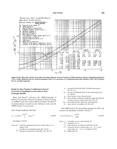
Figure 10-147. Shell-side j H factors for bundles. One sealing strip per 10 rows of tubes and TEMA clearances. (Source: Engineering Data Book,
2 Ed., ©1960. Wolverine Tube, Inc. Used by permission: Kern, D. Q., and Kraus, A. D. Extended Surface Heat Transfer, p. 506, ©1972. McGraw-
nd
Hill, Inc. All rights reserved.)
viscosity of shell-side fluid (at bulk temperature)
Design for Heat Transfer Coefficients by Forced
lb/(ft) (hr)
Convection Using Radial Low-Fin tubes in Heat
w viscosity of shell-side fluid at tube wall temperature,
Exchanger Bundles
lb/(ft)(hr)
j H heat transfer factor, dimensionless
Kern and Kraus 206 reference the ASME-University of
h o heat transfer coefficient for fluid outside tubes based
Delaware Cooperative Research Program on Heat Exchang- on tube external surface, Btu/(hr) (ft )(°F)
2
ers by Bell 207 and later work by Bell and Tinker. The Kern 206 Re s Reynolds Number, shell side, dimensionless
recommendation is based on the Delaware work and the G s mass velocity (cross-flow), lb/(hr) (ft )
2
TEMA details of construction.
The baffle used in the preceding equation has 20% seg-
Heat Transfer Coefficient, Shell Side mental cuts. Shell-side cross-flow velocity: 206
1c p
2 1>3 d s C¿B
h o j H 3k>D e 4 1
>
w 2 0.14 (10-236) Cross-flow area, a s (10-237)
k 144p
See Figure 10-147. where a s cross-flow area in a tube bundle, ft 2
d s shell-side I.D., in.
where D e shell-side equivalent diameter outside tubes, ft, see p tube pitch, in., see Figures 10-56 and 10-148
Figure 10-56 C clearance between low-fin tubes, (p d e ), or for
c p specific heat of shell-side fluid, Btu/(lb-°F) plain tubes, (p d), in., see Figure 10-148.
k thermal conductivity of fluid, Btu/(ft) (hr)(°F) B baffle pitch, in.