
Page 264 - Applied Process Design For Chemical And Petrochemical Plants Volume III
P. 264
66131_Ludwig_CH10G 5/30/2001 4:38 PM Page 226
226 Applied Process Design for Chemical and Petrochemical Plants
Nucleate Boiling Outside Horizontal or Vertical Tubes
Nucleate boiling is boiling at the tube surface at a tem-
perature difference between outside tube surface tempera-
ture and the fluid body, less than the critical temperature
difference. At and beyond the critical temperature differ-
ence, metastable and film boiling take place. These produce
lower transfer coefficients as the temperature difference
increases.
The nucleate region is the one of interest in most plant
design as previously described for plain tube boiling. The
critical temperature difference curves have been deter-
mined experimentally for a reasonable number of fluids
and should be used whenever possible.
Design Procedure for Boiling, Using Experimental Data
The method suggested by Katz, et al., 69 is logical when
using experimental data:
1. Determine the heat duty by the usual procedures and
define the boiling temperature on the shell side.
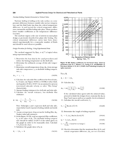
2. Determine the arithmetic average of tube side temper- Figure 10-150. Boiling coefficients for low-finned tubes. (Used by
ature, t a . permission: Katz, D. L., Meyers, J. E., Young, E. H., and Balekjian, G.
Petroleum Refiner, V. 34, No. 2, ©1955. Gulf Publishing Company. All
3. Determine overall temperature drop, t o , from average
rights reserved.)
tube side temperature, t a , to shell-side boiling tempera-
ture, t s .
Then, R t
t oa t a t s (10-239)
R t B 1>h b
4. Calculate the tube-side film coefficient for finned tube,
h t . If water, use Figure 10-50A or 10-50B; if other fluid,
10. Calculate t b :
use Equation 10-44 or 10-47. Use an assumed or process
determined tube-side velocity or other “film fixing”
1 1 r b
characteristic. t b t o a ba b t o a b (10-242)
5. Assume fouling resistances for shell side and tube side. h b R t R t
6. Calculate the overall resistance, less shell-side film
If the calculated value agrees with the assumed value,
resistance:
proceed to finish the design; if not, reassume the t b in
Step 7 and repeat until an acceptable check is obtained.
1 A o A o
B R t r i r o (10-240) 11. Calculate the overall coefficient, U o .
h b A i h t A i
1
Note: Subscripts s and t represent shell and tube side, U o Btu>hr 1ft 21°F2 (10-243)
2
respectively; b and i represent boiling outside and inside R t
tube.
12. Determine the length of tubing required:
7. Assume a temperature drop across the boiling film, t b .
Neglect tube wall resistance.
U L U c 1A o 2, Btu>hr 1lin ft21°F2 (10-244)
8. From Figure 10-150, read an expected film coefficient,
h b , at the value of t b . The shell-side boiling tempera-
Q U L L t t oa , Btu>hr (10-245)
ture should be within 15–20°F of the values given on
the graph in order to be reasonably close. Calculate Q
L t , f 1total for exchanger2 (10-246)
1/h b from the chart. U L t o
9. Substitute the graph value of h b in
13. Check to determine that the maximum flux, Q/A, and
R t 1>h b B (10-241) critical temperature difference, t o , are not exceeded,