Page 269 - Applied Process Design For Chemical And Petrochemical Plants Volume III
P. 269

66131_Ludwig_CH10G  5/30/2001 4:38 PM  Page 231


                                                                    Heat Transfer                                          231

                                         Table 10-41
                           Estimating Overall Heat Transfer Rates, U o ,
                            for Longitudinal Finned Heat Exchangers

                     With water for cooling or steam for heating, these are estimated
                     values for preliminary study only.

                     Process                         Estimated Overall
                                                        Rates “U o ”
                     Heating viscous materials
                       Double pipe—cut & twist fins        12
                       Multitube bare tubes                15
                     Medium HC viscosity 3—15 cp avg.
                       Heating—double pipe w/fins          15
                               Multitube bare tube         25
                       Cooling—double pipe w/fins          12
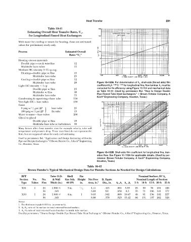
                               Multitube bare tube         20              Figure 10-153A. For determination of h o , shell-side (finned side) film
                     Light HC viscosity   1 cp                             coefficient h o K  0.667 C  0.333  for longitudinal fins, flow laminar. h o must be
                               Double pipe w/fins          25              corrected for fin efficiency using Figure 10-154 and mechanical data
                                                                           as Table 10-42. (Used by permission: Bul. “How to Design Double
                               Multitube w/fins            40
                                                                           Pipe Finned Tube Heat Exchangers.” © Brown Fintube Company, A
                               Multitube bare tube         75
                                                                           Koch Engineering Company, Houston, Texas.)
                                                                               ®
                     Condensing & vaporizing—bare tube     150
                     Very light HC—bare tubes              150
                     Gases
                              1
                       0 psig w/ / 2 psi  P             bare tube  25
                                        }
                       100 psig w/1 psi  P            fin tube  15
                     Water to water—bare tubes             200
                     Glycol to glycol
                               Double pipe w/fins          10
                               Multitube bare tube w/turbulators  30
                     Many factors affect heat transfer rates for example velocity, tube wall
                     temperature and pressure drop. These rates listed do not represent the
                     limit, but are suggested values for study and estimating.
                     Used by permission: Bul. “Application and Design Estimating of Double
                                                              ®
                     Pipe and Hairpin Exchangers.” © Brown Fintube Co., A Koch Engineering
                     Co., Houston, Texas.

                                                                           Figure 10-153B. Shell-side film coefficient for longitudinal fins, tran-
                                                                           sition flow. See Figure 10-153A for applicable details. (Used by per-
                                                                           mission: Brown Fintube Company, A Koch Engineering Company,
                                                                                                           ®
                                                                           Houston, Texas.)
                                                                    Table 10-42
                            Brown Fintube’s Typical Mechanical Design Data for Fintube Sections As Needed for Design Calculations

                                                                                                                        2
                       BFT                 Tube O.D.   Shell   Fin                                      Nominal Surface, Ft A o
                      Section  No.   No.     & Wall  Size Sch. Height  Net Free  D e Equiv.           Nominal Length of Section
                       Type   Tubes  Fins  Thick (in.)  40 IPS  in.  Area, in. 2  Dia., in.  A f ,A o A o ,A i  5 ft  10 ft 15 ft 20 ft  25 ft
                       X51      1     24    1.900      3 in.   1 / 2   4.11     .415     .801  5.93  25    50   76  101   126
                                      36      .145                     3.89      301     .858  8.3   35    71   106  141  177
                       X53      1     24    1.900      4 in.    1      9.03     .542     .889  10.67   45   91  136  182   227
                                      36      .145                     8.60     .379     .923  15.42  66  131   197  262  328
                     Notes:
                     1. Fin thickness equals 0.035 in. (narrow web).
                     2. A f /A o ratio of fin surface to total external heated surface.
                     3. A o /A i ratio of total external heated surface to inside tube surface.
                                                                                                    ®
                     Used by permission: “How to Design Double-Pipe Finned Tube Heat Exchangers.” ©Brown Fintube Co., A Koch Engineering Co., Houston, Texas.
   264   265   266   267   268   269   270   271   272   273   274