
Page 268 - Applied Process Design For Chemical And Petrochemical Plants Volume III
P. 268
66131_Ludwig_CH10G 5/30/2001 4:38 PM Page 230
230 Applied Process Design for Chemical and Petrochemical Plants
steel, aluminum, aluminum bronze, stainless steel, admi- can be fabricated with more than one finned tube in a larger
ralty, copper, copper-nickel, monel, and chrome moly alloy. shell. The fins are more effective or beneficial when the fin-
This longitudinal fin style unit can be used in cross- side film coefficient is lower than the inside tube coefficient;
exchange, kettle-type reboilers, chillers, and condensers. therefore, the poorest heat transfer fluid conditions are best
The rating/design of longitudinal finned tubes is presented used on the finned side of the tube.
by Brown Fintube Co. in an unnumbered bulletin, refer-
ence 211. The double pipe finned tube, Figure 10-4A, is Finned Side Heat Transfer
often applicable for gas, viscous liquids, or small volumes,
and the economics favor high operating pressure due to the For a double pipe exchanger (one finned tube in each of
small diameter shell. 211 They operate well in dirty or some- two shells), see Figure 10-4A, the heat flow resistances are 211
what fouling conditions due to the ease of cleaning. Units
a. Film resistances on outside of the tube, h o .
b. Metal tube wall resistance, R m
c. Film resistance on inside of tube, h i .
d. Note that fouling resistance on tube finned side and
inside tube must be added.
(10-248)
1>U o 1>h o 1>h i R m
2
where U o , h o , h i Btu/(hr) (ft )(°F)
2
R m (hr)(ft ) (°F)/BTU
e. See Table 10-41 for suggested overall U coefficients and
Table 10-42 for mechanical data.
Figure 10-46 gives the usual Sieder-Tate chart and equa-
tion for tube-side, bare-tube heat transfer. For the finned
shell-side heat transfer, see Figures 10-153A, 10-153B,
10-153C 211 or the recommendation of Kern and Kraus, 206
Figure 10-154.
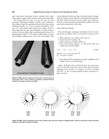
Figure 10-152A. Typical longitudinal finned tubes. Uninterrupted and
Interrupted G-Fin ® Tubes. (Used by permission: Griscom-Russell,
Ecolaire Corp.) (Also see Figure 10-4A(3).)
Figure 10-152B. Typical longitudinal finned tubes. Relative pipe sizes and number of longitudinal fins. (Used by permission: Griscom-Russell,
Ecolaire Corp.) (Also see Figure 10-4A(3).)