
Page 273 - Applied Process Design For Chemical And Petrochemical Plants Volume III
P. 273
66131_Ludwig_CH10G 5/30/2001 4:38 PM Page 235
Heat Transfer 235
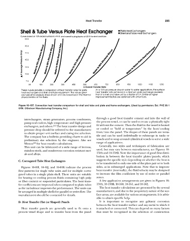
Figure 10-157. Convection heat transfer comparison for shell and tube and plate and frame exchangers. (Used by permission: Bul. PHE 96-1
6/96. ©Graham Manufacturing Company, Inc.)
through a good heat transfer cement and into the wall of
interchangers, steam generators, process condensers,
the process vessel, or can be used to create a physically tight
pump seal coolers, high temperature and high pressure
exchangers, and others. 212 The heat transfer design and fit without the cement. Then the fluid in the vessel is heated
or cooled or “held at temperature” by the heat/cooling
pressure drop should be referred to the manufacturer
from/into the panel. The shapes of these panels are versa-
to obtain proper unit surface and casing size selection.
tile and can be used individually to submerge in tanks or
The company has a bulletin providing charts to aid in
vessels and to wrap around cylindrical vessels to serve a wide
preliminary size selection by the engineer. Also see
Minton 268 for heat transfer calculations. range of applications.
Generally, two styles and techniques of fabrication are
This unit can be fabricated of a wide range of ferrous,
used, but may vary between manufactures, see Figures 10-
stainless steels, and nonferrous corrosion resistant met-
158A and 10-158B. Note the importance of good flow distri-
als and alloys.
bution in between the heat transfer plates/panels, which
suggests the specific style depending on whether the heat is
C. Corrugated Tube Heat Exchangers
to be transferred to only one side of the plate pair or to both
Figures 10-10I, 10-10J, and 10-10K indicate the process sides, as in submerged applications. Note that to improve
flow patterns for single tube units and for multiple corru- heat transfer (internally), the fluid velocity may be designed
gated tubes in a single plain shell. These units are suitable to increase the film coefficient by use of series or parallel
for heating or cooling process fluids containing high pulp zones.
or fiber content or suspended particulates. The heat trans- A few application arrangements are given in Figures 10-
fer coefficients are improved when compared to plain tubes 159A, 10-159B, 10-160, 10-161, and 10-162.
as the turbulence improves the performance. The units can The heat transfer calculations are presented by the several
be arranged in multiple shells for parallel or series flow. The manufacturers, and due to the proprietary nature of the sur-
manufacturers should be contacted for details. face areas, are available for various arrangements. It is advis-
able to obtain specific help.
D. Heat Transfer Flat (or Shaped) Panels It is important to recognize any galvanic corrosion
between the heat transfer surface and any metal to which it
Heat transfer panels are generally used to fit onto a is attached or connected. This can depend on many factors
process vessel shape and to transfer heat from the panel that must be recognized in the selection of construction