
Page 278 - Applied Process Design For Chemical And Petrochemical Plants Volume III
P. 278
66131_Ludwig_CH10G 5/30/2001 4:39 PM Page 240
240 Applied Process Design for Chemical and Petrochemical Plants
Table 10-43
Comparison of Bayonet, U-Tube, and Fixed Tubesheet Heat Exchangers
Design Advantages Limitations Applications and Notes
Bayonet Removable tube bundle Double tubesheet Commonly used for heating or cooling very corrosive
permits easy internal increases initial cost. fluids that require expensive corrosion-resistant
cleaning. Design allows materials. Less economical than U-tube design for
free expansion of tubes in in-tank heating.
high-temperature service.
Needs no expansion joint
if shell is used.
U-tube Elimination of one tubesheet Bends make mechanical Recommended for high-pressure ( 600 psi), high-
reduces initial cost. Tube cleaning of tube temperature applications. Tube shape allows extreme
bundle is removable for interiors difficult. Also, temperature differences ( T 250°F) across the
inspection and cleaning. Full only a few outer bends bundle. Often used as integral column bottom
tube bundle minimizes shell- can be replaced, so reboiler and as tank suction heater to preheat
side bypassing. U-bends retubing usually product before pumping. Tube side cannot be made
permit each tube to expand involves replacement single-pass.
and contract individually. of all tubes.
Tube bundle expansion is
independent of shell; no
expansion diaphragm is
required.
2
Fixed-tubesheet Lower cost per ft of heat- Differential expansion Almost universal application unless a removable tube
transfer surface. Replaceable must be accommodated bundle is required for exterior inspection and
straight tubes allow for easy by an expansion joint. cleaning, which may be avoided by running the
internal cleaning. Full tube Gasket failure can fouling fluid on the accessible tube side. Completely
bundle minimizes shell-side allow tube-side fluid closed shell side eliminates gasket leakage. Excellent
bypassing. No packed joints to escape to the for high-vacuum work. Also available in double-
or internal gaskets, so hot atmosphere. tubesheet design to eliminate cross-contamination.
and cold fluids cannot mix
due to gasket failure.
Used by permission: Corsi, R. Chemical Engineering Progress, V. 88, No. 7, p. 32, ©1992. American Institute of Chemical Engineers, Inc. All rights reserved.
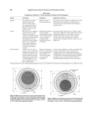
Figure 10-166A. Cross-sectional view of pipe with bare single tracer.
Requirements may dictate 2 or 3 tracer pipes/tubes strapped to pipe
at generally equal spacing around circumference, then insulated. Figure 10-166B. Cross-sectional view of pipe and tracer with thermal
(Used by permission: Foo, K. W. Hydrocarbon Processing, V. 73, No. conducting cement. (Used by permission: Foo, K. W. Hydrocarbon
1, Part 1, ©1994. Gulf Publishing Company.) Processing, V. 73, No. 1, Part. 1, ©1994. Gulf Publishing Company.)