
Page 275 - Applied Process Design For Chemical And Petrochemical Plants Volume III
P. 275
66131_Ludwig_CH10G 5/30/2001 4:39 PM Page 237
Heat Transfer 237
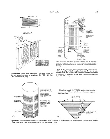
Figure 10-161. This figure illustrates an individual multizone Plate-
coil ® as typically installed in agitated vessels. The stress pads,
hemmed edges, and manifolds are omitted for clarity. Installation may
®
Figure 10-159B. Typical styles of Platecoil . Other styles include ver- be completed by welding or bolting. (Used by permission: Cat. 5-63,
tical and serpentine. (Used by permission: Cat. PCC-1-25M-RLB- Sept. 1994. ©Tranter , Inc.)
®
®
1290, ©1990. Tranter , Inc.)
(A) (B)
Figure 10-160. Platecoils on tank walls and cone bottoms. Note: See Figure 10-163 for use of heat transfer mastic between vessel and heat
®
®
transfer coils/plates. (Used by permission: Bul. 5-63, ©1994. Tranter , Inc..)