
Page 271 - Applied Process Design For Chemical And Petrochemical Plants Volume III
P. 271
66131_Ludwig_CH10G 5/30/2001 4:38 PM Page 233
Heat Transfer 233
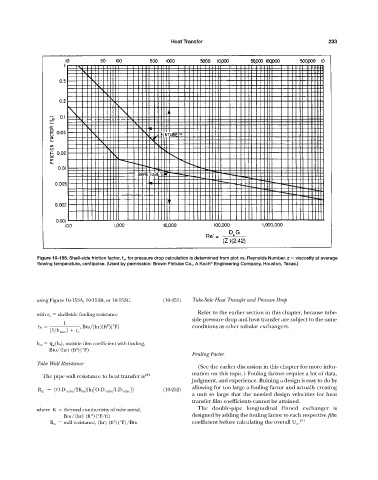
Figure 10-155. Shell-side friction factor, f o , for pressure drop calculation is determined from plot vs. Reynolds Number. z viscosity at average
®
flowing temperature, centipoise. (Used by permission: Brown Fintube Co., A Koch Engineering Company, Houston, Texas.)
using Figure 10-153A, 10-153B, or 10-153C. (10-251) Tube-Side Heat Transfer and Pressure Drop
Refer to the earlier section in this chapter, because tube-
with r o shell-side fouling resistance
side pressure drop and heat transfer are subject to the same
1
2
h f , Btu>1hr21ft 21°F2 conditions as other tubular exchangers.
11>h bare 2 r o
h of h w (h f ), outside film coefficient with fouling,
2
Btu/(hr) (ft )(°F)
Fouling Factor
Tube Wall Resistance
(See the earlier discussion in this chapter for more infor-
mation on this topic.) Fouling factors require a lot of data,
The pipe wall resistance to heat transfer is 211
judgment, and experience. Ruining a design is easy to do by
allowing for too large a fouling factor and actually creating
R m 1O.D. tube >2K m 21ln3O.D. tube >I.D. tube 42 (10-252)
a unit so large that the needed design velocities for heat
transfer film coefficients cannot be attained.
where K thermal conductivity of tube metal, The double-pipe longitudinal finned exchanger is
Btu/(hr) (ft )(°F/ft) designed by adding the fouling factor to each respective film
2
R m wall resistance, (hr) (ft )(°F)/Btu coefficient before calculating the overall U o . 211
2