Page 272 - Applied Process Design For Chemical And Petrochemical Plants Volume III
P. 272

66131_Ludwig_CH10G  5/30/2001 4:38 PM  Page 234


                       234                       Applied Process Design for Chemical and Petrochemical Plants

                       Finned Side Pressure Drop                             A. Plate and Frame Heat Exchangers

                         Brown 211  recommends:                                Figures 10-7, 10-7A, 10-7B, and 10-7C illustrate the gen-
                                                                             eral arrangements of most manufacturers, although several
                                           2
                             10.00043221f o 21G¿2 L                          variations of plate flow pattern designs are available to
                        P                                          (10-253)
                              1D e 21Z>Z w 2 0.14 1 2                        accomplish specific heat transfer fluids’ temperature
                                                                             exchanges. Also, the gasket sealing varies, and some styles
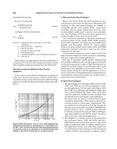
                         Use Figure 10-156 to determine f o .                are seal welded (usually laser) to prevent cross-contamina-
                                                                             tion. Note that Figure 10-7C has no interplate gaskets and is
                              D e G                                          totally accessible on both sides, yet easy to clean.
                       Re                                          (10-254)
                            1Z212.422                                          The construction materials for the plates include most
                                                                             corrosion-resistant metals, usually 304SS, 316SS, titanium,
                                                                                                ®
                                                                                       ®
                       where D e   equivalent annulus diameter, ft; (see earlier   Incoloy 825 , Hastelloy , and others, plus nonmetallic fused
                                                                                                               ®
                                calculation)                                 graphite, and fluoroplastic Diabon F . Typical gaskets
                            G   flow, lb/(ft )(hr)   3,600 (G )              between the plates include nitrile rubber, butyl, and EPDM
                                         2
                                         2
                            G    flow, lb/(ft )(sec)                                            ®         ®
                                                                             elastromers, Hypalon and Viton , based on the various
                             Z   viscosity, average, centipoise
                                                                             manufacturers’ literature.
                                fluid density, lb/ft 3
                                                                               A heat transfer comparison is made in Figure 10-157. The
                             L   equivalent length of travel, including bend factor, ft
                                                                             plate and frame designs are used in convection, condensing,
                            D   tube I.D., ft.
                                                                             and some evaporation/boiling applications.
                                                                               This type of exchanger usually provides relatively high
                         After designing an approximate unit area requirement, it
                                                                             heat transfer coefficients and does allow good cleaning by
                       is important to review the final design performance details
                                                                             mechanically separating the plates, if back-flushing does not
                       with a qualified exchanger manufacturer. See Table 10-42.
                                                                             provide the needed cleanup. An excellent discussion on the
                                                                             performance and capabilities is presented by Carlson. 210  To
                       Miscellaneous Special Application Heat Transfer
                                                                             obtain a proper design for a specific application, it is neces-
                       Equipment
                                                                             sary to contact the several manufacturers to obtain their rec-
                         It is necessary to work with the manufacturer in sizing and  ommendations, because the surface area of these units is
                       rating these special units, because sufficient public data/  proprietary to the manufacturer.
                       correlation of heat transfer does not exist to allow the design
                                                                             B. Spiral Heat Exchangers
                       engineer to handle the final and detailed design with confi-
                       dence.                                                  1. The spiral design heat exchangers, Figures 10-9A, 10-9B,
                                                                                 10-9C, and 10-9D are conveniently adaptable to many
                                                                                 process applications. The true spiral units (Figure 10-9A
                                                                                 and 10-9B) are usually large and suitable for higher flow
                                                                                                    ®
                                                                                 rates, and the Heliflow -style, Figure 10-9C, can be fabri-
                                                                                 cated into small sizes, suitable for many “medium” (but
                                                                                 not limited) process and sample cooler applications.
                                                                                 The spiral units are used as cross-flow interchangers,
                                                                                 condensers, and reboilers. These units can often be con-
                                                                                 veniently located to reduce space requirements. They
                                                                                 are suitable for vacuum as low as 3mm Hg, because the
                                                                                 pressure drops can be quite low. Bailey 214  identifies tem-
                                                                                 perature limits of  30 to 	1,500°F, pressure limits of 0
                                                                                 to 350 psia, maximum flow rate per shell of 3,000 gpm,
                                                                                                              2
                                                                                 and a heat transfer area of 4,000 ft . Trom 213  discusses a
                                                                                 wide variety of process-related applications.
                                                                                            ®
                                                                               2. The Heliflow is a tubular version of the spiral plate
                                                                                 heat exchanger, Figures 10-9C and 10-9D, and has a
                                                                                 high efficiency and counter-flow operation with a wide
                       Figure 10-156. Heat-transfer curve for annuli with longitudinal fins.  range of applications while occupying a limited space.
                       (Adapted from DeLorenzo, B., and Anderson, E. D. Trans ASME, V. 67,
                       No. 697, ©1945. The American Society of Mechnical Engineers) (Used  The applications include vent condensing, sample cool-
                       by permission: Kern, D. Q., and Kraus, A. D. Extended Surface Heat  ers, instantaneous water heating, process heating and
                       Transfer, p. 464, ©1972. McGraw-Hill, Inc. All rights reserved.)  cooling, reboilers and vaporizers, cryogenic coolers,
   267   268   269   270   271   272   273   274   275   276   277