
Page 277 - Applied Process Design For Chemical And Petrochemical Plants Volume III
P. 277
66131_Ludwig_CH10G 5/30/2001 4:39 PM Page 239
Heat Transfer 239
resulting mixture can be set for the desired temperature for
direct mixing, heating jackets of vessels, and similar require-
ments, see Figures 10-163 and 10-164.
F. Bayonet Heat Exchangers
Bayonet heat exchangers are modified shell and tube
types. The tubes are concentric with the outer tube, being
sealed closed at one end, although the shell in its entirety is
not always used or needed, see Figure 10-165. A helpful arti-
cle describing this type of unit is by Corsi. 216
A useful application is for tank and vessel heating, with
the heater protruding into the vessel. Bayonet heat exchang-
ers are used in place of reactor jackets when the vessel is
large and the heat transfer of a large mass of fluid through
the wall would be difficult or slow, because the bayonet can
have considerably more surface area than the vessel wall for
transfer. Table 10-43 compares bayonet, U-tube, and fixed-
tubesheet exchangers. 216
The outer and inner tubes extend from separate station-
ary tube sheets. The process fluid is heated or cooled by heat
transfer to/from the outer tube’s outside surface. The over-
all heat transfer coefficient for the O.D. of the inner tube is
found in the same manner as for the double-pipe
70
exchanger. The equivalent diameter of the annulus uses
the perimeter of the O.D. of the inner tube and the I.D. of
70
the inner tube. Kern presents calculation details.
G. Heat-Loss Tracing for Process Piping
The two basic types of systems for maintaining and/or
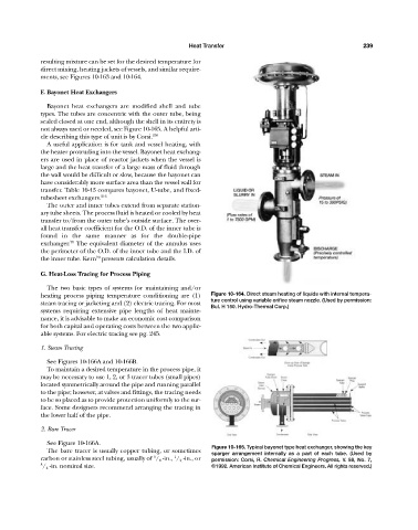
heating process piping temperature conditioning are (1) Figure 10-164. Direct steam heating of liquids with internal tempera-
ture control using variable orifice steam nozzle. (Used by permission:
steam tracing or jacketing and (2) electric tracing. For most
Bul. H 150. Hydro-Thermal Corp.)
systems requiring extensive pipe lengths of heat mainte-
nance, it is advisable to make an economic cost comparison
for both capital and operating costs between the two applic-
able systems. For electric tracing see pg. 245.
1. Steam Tracing
See Figures 10-166A and 10-166B.
To maintain a desired temperature in the process pipe, it
may be necessary to use 1, 2, or 3 tracer tubes (small pipes)
located symmetrically around the pipe and running parallel
to the pipe; however, at valves and fittings, the tracing needs
to be so placed as to provide protection uniformly to the sur-
face. Some designers recommend arranging the tracing in
the lower half of the pipe.
2. Bare Tracer
See Figure 10-166A.
Figure 10-165. Typical bayonet type heat exchanger, showing the key
The bare tracer is usually copper tubing, or sometimes sparger arrangement internally as a part of each tube. (Used by
3
1
carbon or stainless steel tubing, usually of / 8 -in., / 2 -in., or permission: Corsi, R. Chemical Engineering Progress, V. 88, No. 7,
3 / 4 -in. nominal size. ©1992. American Institute of Chemical Engineers. All rights reserved.)