
Page 282 - Applied Process Design For Chemical And Petrochemical Plants Volume III
P. 282
66131_Ludwig_CH10G 5/30/2001 4:40 PM Page 244
244 Applied Process Design for Chemical and Petrochemical Plants
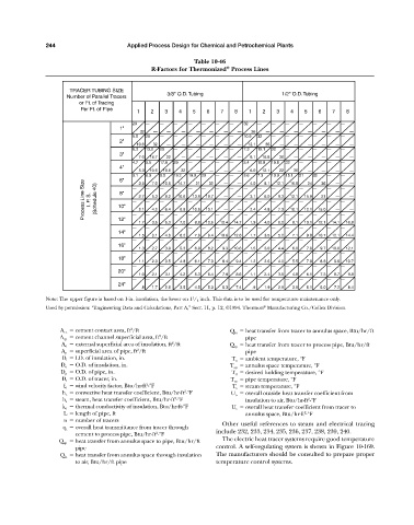
Table 10-46
®
R-Factors for Thermonized Process Lines
TRACER TUBING SIZE
Number of Parallel Tracers 3/8" O.D. Tubing 1/2" O.D. Tubing
or Ft. of Tracing
Per Ft. of Pipe
1 2 3 4 5 6 7 8 1 2 3 4 5 6 7 8
29 — — — — — — — 32 — — — — — — —
1"
32 — — — — — — — 36 — — — — — — —
9.5 29 — — — — — — 10.9 32 — — — — — —
2"
10.6 32 — — — — — — 12.1 36 — — — — — —
6.3 13.2 29 — — — — — 7.3 15.1 32 — — — — —
3"
7.0 14.7 32 — — — — — 8.1 16.8 36 — — — — —
4.7 9.5 17.6 29 — — — — 5.4 10.9 19.8 32 — — — —
4"
5.3 10.6 19.6 32 — — — — 6.0 12.1 22 36 — — — —
3.1 3.5 6.3 7.0 9.5 10.6 13.2 18.9 21 29 32 — — — — 3.6 4.0 7.3 8.1 10.9 15.1 21 24 32 36 — — — —
Process Line Size I. P . S. (Schedule 40) 10" — 2.7 — 5.3 — 8.2 — 10.6 — 13.9 — 18.7 — — — — — 3.1 — 6.0 — 9.3 — 12.1 — 15.9 — 15.0 — — — —
6"
16.8
14.7
12.1
8"
21
—
—
—
—
—
—
—
—
—
—
—
—
—
—
—
—
—
7.3
2.4
12.1
—
2.1
—
10.1
10.6
8.9
6.4
4.2
4.8
13.1
—
—
12"
1.7 — 3.5 — 5.3 — 7.0 — 8.9 — 10.6 — 12.4 — 14.7 — 1.9 — 4.0 — 6.0 — 8.1 — 10.1 — 12.1 — 14.1 — 16.8
— — — — — — — — — — — — — — — —
14"
1.5 3.1 4.6 6.2 7.9 9.4 10.6 12.6 1.7 3.5 5.2 7.1 9.0 10.7 12.1 14.4
— — — — — — — — — — — — — — — —
16"
1.3 2.7 3.9 5.3 6.9 8.2 9.3 10.6 1.5 3.0 4.4 6.0 7.8 9.7 10.6 12.1
— — — — — — — — — — — — — — — —
18"
1.1 2.3 3.5 4.8 6.1 7.3 8.4 9.4 1.2 2.6 4.0 5.5 7.0 8.3 9.6 10.7
— — — — — — — — — — — — — — — —
20"
1.0 2.1 3.1 4.2 5.3 6.4 7.6 8.6 1.1 2.4 3.5 4.8 6.1 7.3 8.7 9.8
— — — — — — — — — — — — — — — —
24"
.8 1.7 2.6 3.5 4.5 5.3 6.3 7.4 .9 1.9 2.9 3.9 5.1 6.0 7.2 8.4
Note: The upper figure is based on 1-in. insulation, the lower on 1 / 2 inch. This data is to be used for temperature maintenance only.
1
Used by permission: “Engineering Data and Calculations, Part A,” Sect. 11, p. 12, ©1994. Thermon Manufacturing Co./Cellex Division.
®
2
A cc cement contact area, ft /ft Q ta heat transfer from tracer to annulus space, Btu/hr/ft
2
A cp cement channel superficial area, ft /ft pipe
2
A o external superficial area of insulation, ft /ft Q tp heat transfer from tracer to process pipe, Btu/hr/ft
2
A p superficial area of pipe, ft /ft pipe
D i I.D. of insulation, in. T a ambient temperature, °F
D o O.D. of insulation, in. T ap annulus space temperature, °F
D p O.D. of pipe, in. T d desired holding temperature, °F
D t O.D. of tracer, in. T m pipe temperature, °F
2
f o wind velocity factor, Btu/hr-ft -°F T s steam temperature, °F
2
h c convective heat transfer coefficient, Btu/hr-ft -°F U o overall outside heat transfer coefficient from
2
h s steam, heat transfer coefficient, Btu/hr-ft -°F insulation to air, Btu/hr-ft -°F
2
k o thermal conductivity of insulation, Btu/hr-ft-°F U t overall heat transfer coefficient from tracer to
2
L length of pipe, ft annulus space, Btu/hr-ft -°F
n number of tracers
Other useful references to steam and electrical tracing
q t overall heat transmittance from tracer through
2
cement to process pipe, Btu/hr-ft -°F include 232, 233, 234, 235, 236, 237, 238, 239, 240.
The electric heat tracer systems require good temperature
Q ap heat transfer from annulus space to pipe, Btu/hr/ft
pipe control. A self-regulating system is shown in Figure 10-169.
Q ia heat transfer from annulus space through insulation The manufacturers should be consulted to prepare proper
to air, Btu/hr/ft pipe temperature control systems.