
Page 281 - Applied Process Design For Chemical And Petrochemical Plants Volume III
P. 281
66131_Ludwig_CH10G 5/30/2001 4:40 PM Page 243
Heat Transfer 243
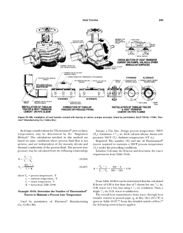
Figure 10-168. Installation of heat transfer cement with tracing on valves, pumps, and pipe. (Used by permission: Bul.T-109-M, ©1994. Ther-
®
mon Manufacturing Co./ Cellex Div.)
®
In design considerations for Thermonized process lines, Assume a 3-in. line. Design process temperature: 320°F
1
temperatures may be determined by the “Stagnation (T p ). Insulation: 1 / 2 -in. thick calcium silicate. Steam tem-
Method.” The calculations involved in this method are perature: 366°F (T s ). Ambient temperature: 0°F (t a ).
based on static conditions where process fluid flow is not Required: The number (N) and size of Thermonized ®
present, and are independent of the viscosity, density and tracers required to maintain a 320°F process temperature
thermal conductivity of the process fluid. The process tem- (T p ) under the preceding conditions.
perature may be calculated from the following relationship: Solution: Calculate the R factor and determine the tracer
requirements from Table 10-46.
T p t a
R (10-266)
T s T p
RT s t a
T p (10-267) T p t a 320 0
1 R R 6.96
T s T p 366 320
where T p process temperature, °F
t a ambient temperature, °F
T s steam temperature, °F From Table 10-46 it can be determined that the calculated
3
R factor from Table 10-46 R factor of 6.96 is less than that of 7 shown for one / 8 -in.
1
O.D. tracer on a 3-in. line using 1 / 2 -in. insulation. Thus, a
3
Example 10-24. Determine the Number of Thermonized ® single / 8 -in. O.D. tracer is satisfactory.
Tracers to Maintain a Process Line Temperature The overall heat transmittance from tracer through heat
transfer cement to process pipe, q t , in Btu/(hr) (ft )(°F) is
2
Used by permission of Thermon ® Manufacturing given in Table 10-47. 223 From the detailed articles of Foo, 223
Co./Cellex Div. the following nomenclature applies: