
Page 283 - Applied Process Design For Chemical And Petrochemical Plants Volume III
P. 283
66131_Ludwig_CH10G 5/30/2001 4:40 PM Page 245
Heat Transfer 245
Table 10-47 where D pipe diameter, in.
Heat Transmittance from Tracers through Heat Transfer t temperature, °F
Cement to Process Pipe 4 q heat loss through wall, Btu/lin ft
k thermal conductivity of pipe wall,
2
NPS q t Btu/(hr) (ft )(°F/ft)
i inside wall pipe
1 34.3 o outside wall surface of pipe
1.5 34.3
Heat loss from fluid inside pipe through exterior insula-
2 32.6
tion to outside air. Combined convection and radiation:
70
2.5 32.6
3 29.1
1t s t a 2
4 26.9 q , Btu>1hr21lin ft2 (10-269)
6 23.8 12.3>2k c 2 log1D 1 >D s –2 1>1h a D 1 2
8 21.5
10 18.4 where s inside surface of pipe
12 14.6 h a surface coefficient of heat transfer,
2
14 12.2 Btu/(hr) (ft )(°F/ft)
16 9.8 k thermal conductivity of insulation,
2
18 9.8 Btu/(hr) (ft )(°F/ft)
20 9.8 D pipe O.D., ft
D 1 insulation O.D., ft
4 Note: Reference 4 is to Foo’s article’s literature citation. Symbols: NPS
2
nominal pipe size, in.; q t Btu/(hr)(ft )(°F). a bulk fluid outside insulated pipe
q heat loss per linear foot of pipe, Btu/(hr) (lin ft)
Used by permission: Foo, K. W. Hydrocarbon Processing, V. 73, No. 1, ©1994.
Gulf Publishing Company. All rights reserved.)
Selected Values for k, Thermal Conductivity
of Insulation*
2
Material k, Btu/(hr) (ft ) (°F/ft)
Mineral wool 0.28
Foam glass 0.43
Calcium silicate 0.38
Magnesia, 85% 0.38
Glass 0.59-0.79
Glass wool 0.022
*Compiled from references 284 and 223.
Heat loss through the walls of the insulation is 221
®
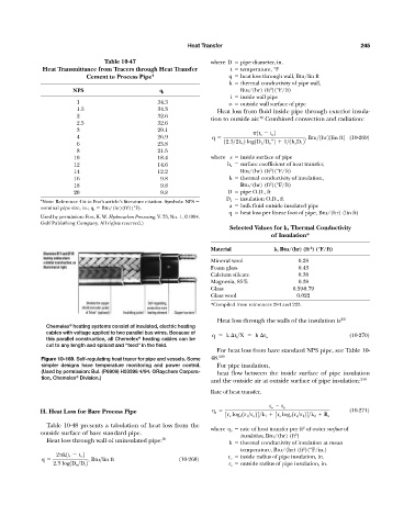
Chemelex heating systems consist of insulated, electric heating
cables with voltage applied to two parallel bus wires. Because of
q k t i >X h t o (10-270)
®
this parallel construction, all Chemelex heating cables can be
cut to any length and spliced and “teed” in the field.
For heat loss from bare standard NPS pipe, see Table 10-
Figure 10-169. Self-regulating heat tracer for pipe and vessels. Some 48. 220
simpler designs have temperature monitoring and power control. For pipe insulation,
(Used by permission: Bul. (P6909) H53398 4/94. ©Raychem Corpora- heat flow between the inside surface of pipe insulation
®
tion, Chemelex Division.)
and the outside air at outside surface of pipe insulation: 248
Rate of heat transfer,
t o t a
H. Heat Loss for Bare Process Pipe q s (10-271)
3r s log e 1r 1 >r o 24>k 1 3r s log e 1r s >r 1 24>k 2 R s
Table 10-48 presents a tabulation of heat loss from the
2
where q s rate of heat transfer per ft of outer surface of
outside surface of bare standard pipe. insulation, Btu/(hr) (ft )
2
Heat loss through wall of uninsulated pipe: 70 k thermal conductivity of insulation at mean
2
temperature, Btu/(hr) (ft )(°F/in.)
2 k1t i t o 2 r o inside radius of pipe insulation, in.
q , Btu>lin ft (10-268)
2.3 log1D o >D i 2 r s outside radius of pipe insulation, in.