Page 288 - Applied Process Design For Chemical And Petrochemical Plants Volume III
P. 288

66131_Ludwig_CH10G  5/30/2001 4:40 PM  Page 250


                       250                       Applied Process Design for Chemical and Petrochemical Plants

                         The liquid phase resistance, h la , is considered low when  
  Ackerman correction factor, dimensionless, source
                                                                                      unknown.
                       compared to the overall resistance; therefore, the h ga
                       should give a reasonable approximation to the overall resis-
                       tance for the system, 242, 247  because 1/U a   1/h ga 	 1/h la .  For little or no condensation in the system:

                       B. Random Packed Columns                              1>U a      1>h g a  	  1>h l a
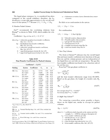
                         Fair 242  recommends the correlating relations from   For condensation:
                       Huang 250  as shown in Table 10-49, which satisfies the rela-
                       tion.                                                 1>U a      1>
h g a  	  11>h l a2 1Q s >Q T 2
                                                          m
                         Coefficient   h g a, or h l a, or U a   C 1 G L n
                                                                                  Sc   Schmidt number, dimensionless
                       where h g a   volumetric gas-phase heat transfer coefficient,  Pr   Prandtl number, dimensionless
                                           3
                                 Btu/(hr) ( ft )(°F)                              c g   gas specific heat, Btu/lb-°F
                                                                                                    2
                            h l a    liquid-phase heat transfer coefficient,       a   interfacial area, ft /ft 3
                                          3
                                 Btu/(hr) (ft )(°F)                               Q s   sensible heat transfer duty, Btu/hr
                            U a   volumetric overall heat transfer coefficient,   Q T   total heat transfer duty, Btu/hr
                                          3
                                 Btu/(hr) (ft )(°F)
                                                               2
                             G    superficial gas mass velocity, lb/(hr) (ft )  C. Sieve Tray Columns
                                                                 2
                             L    superficial liquid mass velocity, lb/(hr) (ft )
                                                                               The thesis of Stewart 249  indicates that the overall liquid
                                                                             film and mass transfer coefficients were functions of the gas
                                           Table 10-49                       flow rate and the column pressure and are independent of
                            Heat Transfer Coefficients for Packed Columns    the liquid flow rate and inlet air temperature. The gas film
                                                                             heat transfer coefficient was found to be a function only of
                                                       m
                                       Coefficient*   C 1 G L n              the air flow rate.
                                                                               From Fair 242  the gas phase coefficient is
                       Packing      System   Coefficient  C 1   m    n
                       RR—1 in.    Air/water    h l a  0.774   0.51  0.63          c g G1Sc g 2 2>3
                                   Air/water    h g a  0.230   1.10  0.02    h g a    H g,d 1Pr g 2                      (10-276)
                                   Air/oil      U a    0.00026  1.69  0.51
                       RR—1.5 in.  Air/water    h l a  0.738   0.48  0.75    and the heat transfer efficiencies range from 60–100%.
                                   Air/water    h g a  0.008   1.45  0.16    Based on the gas phase, the height of a transfer unit, H g ,
                                   Air/oil      U a    0.0016  1.49  0.38    is 242
                       IS—1 in.    Air/water    h l a  2.075   0.20  0.84
                                   Air/water    h g a  0.095   1.01  0.25
                                   Air/oil      U a    0.0045  1.32  0.43    H g,d        G                              (10-277)
                       IS—1.5 in.  Air/water    h l a  6.430   0.20  0.69           k g  a M g  P
                                   Air/water    h g a  0.019   1.38  0.10
                                   Air/oil      U a    0.003   1.44  0.36    For nitrogen data: 242  U a   0.213G 1.0
                       PR—1 in.    Air/water    h l a  0.296   0.45  0.87    For helium data: 242  U a   1.05G 1.0
                                   Air/water    h g a  0.019   1.12  0.33
                                   Air/oil      U a    0.0013  1.47  0.46    D. Baffle Tray Column 242
                       PR—1.5 in.  Air/water    h la   1.164   0.31  0.80
                                   Air/water    h ga   0.011   1.28  0.26      The contacting counterflow action provides a depen-
                                   Air/oil      U a    0.027   1.07  0.36    dence on the liquid rate, similar in concept for packed
                       *h g a or h l a or U a , Btu/(hr-ft -°F)              columns:
                                           3
                       Symbols
                                                                                       m n
                                                                             H g a     C 1 G L                          (10-277A)
                       RR 1 in.  }  Ceramic Raschig rings, 1-in. and 1.5-in. nominal size
                       RR 1.5 in.
                                                                             where C 1   coefficient which depends on the system used, for
                       IS 1 in.  }  Ceramic Intalox saddles, 1-in. and 1.5-in. nominal size  example, C 1   2.058 for nitrogen/absorption oil
                       IS 1.5 in.                                                                            3
                                                                                  h g   heat transfer coefficient, J/m sk
                                                                                                            2
                                                                                                    2
                       PR 1 in.  }  Metal Pall rings, 1-in. and 1.5-in. normal size  a   interfacial area, n /m , or ft /ft 3
                                                                                                       3
                       PR 1.5 in.                                                  c   specific heat, Btu/(lb) (°F)
                                                                                                                    2
                       Used by permission: Fair, J. R. ASME Solar Energy Division Conference,  G   superficial gas mass velocity, lb/(hr) (ft )
                                                                                                                   2
                       April 1989. ©American Society of Mechanical Engineers, San Diego, CA.  h   heat transfer coefficient, Btu/(hr) (ft )(°F)
   283   284   285   286   287   288   289   290   291   292   293