
Page 293 - Applied Process Design For Chemical And Petrochemical Plants Volume III
P. 293
66131_Ludwig_CH10G 5/30/2001 4:41 PM Page 255
Heat Transfer 255
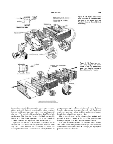
Figure 10-178. Typical tube bundle
using fabricated or cast end head-
ers. (Used by permission: Yuba Heat
Transfer Division of Connell Limited
Partnership.)
Figure 10-179. Typical tube bun-
dle using flanged end cover
plates. (Used by permission:
Yuba Heat Transfer Division of
Connell Limited Partnership.)
these units are isolated, the associated noise would be imme- designs require a pipe inlet or outlet at each end of the tube
diately noticeable but not objectionable unless confined bundle, walkways may be required at each end. Pipe layout
between buildings or structures where reverberation could studies are necessary when multiple sections (exchanger
take place. The noise level is usually limited to 75 decibels bundles) are placed in the same service.
maximum at 50 ft from the fan, and the blade tip speed is The structural parts can be galvanized or pickled and
limited to 11,000–12,000 ft per min ( blade dia. in ft painted to prevent rusting of the steel. The specifications
rpm). This may run higher for units below 48-in. dia. will depend upon local requirements and experience.
Figure 10-175 illustrates the assembly of a typical forced Hail guards of stiff hardware cloth mounted in a remov-
draft unit with electric motor and gear drive. Note that walk- able frame are used to prevent hail damage to the relatively
ways and access ladders are necessary to reach the soft fins in hail-susceptible areas. If damaged just slightly, the
exchanger connections where valves are usually installed. If performance is not impaired.