
Page 296 - Applied Process Design For Chemical And Petrochemical Plants Volume III
P. 296
66131_Ludwig_CH10G 5/30/2001 4:41 PM Page 258
258 Applied Process Design for Chemical and Petrochemical Plants
Figure 10-182. Fan blade guard mounted directly below blades. Note
that drive shaft connects through the opening. (Used by permission:
Bul. 107. SMITHCO Engineering, Inc.)
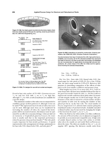
Figure 10-183B. Illustrations of actual fin construction. (Used by per-
mission: Bul. B589-455, 6/89. ©Hudson Products Corporation.)
Counterclockwise from top: (1) Extruded fins offer high performance,
reliability, and economy. (2) Hy-Fin extruded-serrated fins represent
the state-of-the-art in fin tube construction technology. (3) Imbedded
fins are recommended for applications involving high process tem-
peratures. (4) L-base wrap-on fins offer low initial cost for applica-
tions involving low process temperatures.
1-in. / 2-in. / 2.375 in.
1-in. / 2.25 in./ 2.625 in.
For 1-in./2-in. (bare tube O.D./finned tube O.D.) the
usual range for tube pitch is 2.125–2.5. For a 1-in./2.25-in
tube, the pitch range would be 2.375–2.75. Reference 265
presents an interesting comparison of the effects of tube
Figure 10-183A. Fin designs for use with air-cooled exchangers. pitch on the heat transfer coefficient and pressure drop.
Tube lengths vary from 5 ft to more than 30 ft. Units for
some heavy lube oils have been installed without fins due to
finned to bare tube surface of 15:1–20:1. Common sizes are the poor heat transfer inside the tube, i.e., the fins could not
5
3 / 4 -in. and 1-in. O.D. with / 2 -in. to / 8 -in. high fins, improve the overall coefficient above plain tubes. Economi-
1
1
although 1 / 2 -in. O.D. as well as small sizes are available for cal tube lengths usually run 14–24 ft and longer. The per-
a specific design. formance of the tubes is varied for a fixed number of tubes
The minimum number of the tube rows recommended to and number of tube rows by varying the number of fins
establish a proper air flow pattern is 4, although 3 rows can placed per lin in. on the bare tube. The usual number of
be used. 265 The typical unit has 4–6 rows of tubes, but more fins/in. ranges from 7–11, with the lower number giving less
2
can be used. Although more heat can be transferred by total finned surface, ft per lin ft of tube. Available extended
increasing the number of tubes, the required fan horse- or finned surface may be increased by changing the height
1
5
power will be increased; however, this balance must be opti- of the fins from the usual / 2 -in. to / 8 -in.
mized for an effective economical design. Tubes are laid out When the fluid in the tubes yields a low film coefficient,
on transverse or longitudinal patterns; however, the trans- the amount of finned surface area is adjusted, as suggested,
verse is usually used due to the improved performance to provide an economical and compatible area. A high ratio
related to pressure drop and heat transfer. 265 The tube pitch of outside finned surface to bare tube surface is of little
is quite important for best air-side performance. A typical value when the outside air and inside fluid coefficients are
1
representative tube arrangement for design optimization is about the same. The tubes are usually on 2-in. or / 2 -in. tri-
for bare-tube O.D., finned-tube O.D., and tube pitch: 256 angular (60°) spacing. Fin thickness usually varies from