
Page 259 - Applied Process Design For Chemical And Petrochemical Plants Volume III
P. 259
66131_Ludwig_CH10G 5/30/2001 4:38 PM Page 221
Heat Transfer 221
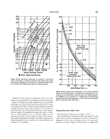
Figure 10-143. Estimating relationship for selection of low-finned
units in oil heaters or coolers; for reference only (1950 costs). (Used
by permission: Williams, R. B. and Katz, D. L. Petroleum Refiner, V. 33,
No. 3, ©1954. Gulf Publishing Company. All rights reserved.)
Figure 10-144. Approximate relationship of the overall coefficient
fouled, and the fouling factor of inside tubes for predicting the eco-
nomical use of finned tubes in shell and tube units. (Used by permis-
sion: Williams, R. B., and Katz, D. L. “Performance of Finned Tubes
Wolverine 21 has presented evaluations of the cost com- and Shell and Tube Heat Exchangers,” ©1951. University of Michigan.
parisons for various types of exchangers and tube materials. Note: For reference only, 1950 costs.)
Figure 10-146 gives a rough indication as to the possible
advantages of a finned tube unit when referenced to a spe-
cific design. If the film coefficients and fouling factors based
on plain tubes are known, the reduction in the number of
finned tubes for the same length and service can be approx- Tubing Dimensions, Table 10-39
imated roughly. The significant saving arises when a reduc-
tion in shell diameter can be effected, based on the For finned tube efficiencies, see Figure 10-147.
estimated reduction in the number of tubes. The results of The fin efficiency is defined by Kern and Kraus 206 as the
this graph should indicate whether a detailed comparison in “ratio of the actual heat dissipation of a fin to its ideal heat
design is justified; keep in mind that the curve is based on an dissipation if the entire fin surface were at the same tem-
average set of conditions. perature at its base.” Figure 10-147 provides a weighted fin