
Page 241 - Applied Process Design For Chemical And Petrochemical Plants Volume III
P. 241
66131_Ludwig_CH10G 5/30/2001 4:37 PM Page 204
204 Applied Process Design for Chemical and Petrochemical Plants
The best designs provide for the percentage vaporization
per pass to have been completed by the time the fluid mixture
reaches the upper end of the tube and the mixture is leaving
to enter the bottom chamber of the distillation column. In
order to assist in accomplishing this, the initial reboiler eleva-
tion should be set to have the top tubesheet at the same level
as the liquid in the column bottom section. A liquid-level con-
trol adjustment capability to raise or lower this bottoms level
must exist to optimize the recirculation. Sometimes, the level
in the bottom of the column may need to be 25–30% of the
reboiler tube length above the elevation of the tubesheet.
Therefore, the vapor nozzle return from the reboiler must
enter at sufficient elevation to allow for this possibility.
Velocities of liquid entering the tubes should be in the
range:
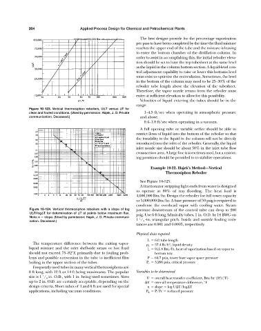
Figure 10-123. Vertical thermosiphon reboilers, U T versus T for
clean and fouled conditions. (Used by permission: Hajek, J. D. Private 1–4.5 ft/sec when operating in atmospheric pressure
communication. Deceased.) and above.
0.4–1.0 ft/sec when operating in a vacuum.
A full opening valve or variable orifice should be able to
restrict flows of liquid into the bottom of the reboiler so that
the instability in the liquid in the column will not be directly
introduced into the inlet of the reboiler. Generally, the liquid
inlet nozzle size should be about 50% in the inlet tube flow
cross-section area. A large line is sometimes used, but a restrict-
ing provision should be provided to to stabilize operations.
Example 10-22. Hajek’s Method—Vertical
Thermosiphon Reboiler
See Figure 10-125.
A fractionator stripping light ends from water is designed
to operate at 80% of tray flooding. The heat load is
4,000,000 Btu/hr. Design the reboiler for full tower capacity
or 5,000,000 Btu/hr. A base pressure of 50 psig is required to
condense the overhead vapor with cooling water. Steam
Figure 10-124. Vertical thermosiphon reboilers with a slope of log pressure downstream of the control valve can drop to 200
U T/log T for determination of T at points below maximum flux. psig. Use 6-ft long Admiralty tubes, 1 in. O.D. by 14 BWG on
Note: n slope. (Used by permission: Hajek, J. D. Private communi- 1
cation. Deceased.) 1 / 4 -in. triangular pitch. Inside and outside fouling resis-
tances are 0.001 and 0.0005, respectively.
Physical data required
L 6 ft tube length
The temperature difference between the exiting vapor- L 57.4 lb/ft , liquid density
3
liquid mixture and the inlet shell-side steam or hot fluid l v 911.8 Btu/lb, heat of vaporization based on vapor to
should not exceed 75–82°F, primarily due to fouling prob- bottom tray
lems and possible conversion in the tube to inefficient film P 64.7 psia, tower base vapor space pressure
boiling in the upper section of the tubes. P c 3,206 psia, critical pressure
Frequently used tubes in many vertical thermosiphons are
8 ft long, with 12 ft or 14 ft being maximums. The popular Variables to be determined
1
size is 1 / 4 in. O.D., with 1 in. being used sometimes. Sizes U overall heat transfer coefficient, Btu/hr (ft )(°F)
2
up to 2 in. O.D. are certainly acceptable, depending on the T over-all temperature difference, °F
design criteria. Short tubes of 4 and 6 ft are used for special n slope log U T/log T
applications, including vacuum conditions. P R P/Pc reduced pressure