
Page 309 - Applied Process Design For Chemical And Petrochemical Plants Volume III
P. 309
66131_Ludwig_CH10G 5/30/2001 4:41 PM Page 268
268 Applied Process Design for Chemical and Petrochemical Plants
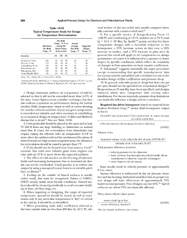
Table 10-50 total surface of the air-cooled unit usually compares favor-
Typical Temperature Study for Design ably cost-wise with a water-cooled unit. 80
Air Temperature Determination 8. For a specific service of desuperheating Freon 11
(180°F) and condensing at 115°F, ambient air at 70°F, total
6
Dry Bulb Q 31.6 10 Btu/hr, Smith 106 points out that for three
Temp., °F; % of Annual
comparative designs with a threefold reduction in fan
Maximum Annual Hr Average Suggested
Dry Bulb Stated Temp. Dry Bulb Design horsepower, a 35% increase occurs in first cost, a 30%
Temp., °F Is Exceeded Temp., °F Temp., °F increase in surface, and a 75% increase in plan area. In
general this trend will apply to all comparisons on design
Location 1% 2% 3%
parameters; of course it is influenced to a greater or lesser
Beaumont, Texas 102 93 91 90 69 91
Victoria, Texas 110 89 96 95 71 96 degree by specific conditions, which reflect the sensitivity
Parkersburg, W. Va. 106 90 87 86 55 87 of changes in flow quantities on heat transfer coefficients.
New Orleans, La. 102 92 91 89 70 91 9. Nakayama suggests essentially the same procedure
87
Wilmington, Del. 106 88 85 84 55 85
Grand Rapids, Mich. 99 83 80 78 47 80 except recommending that specific manufacturers’ data
for various units be assembled and correlated for use in the
Note: 1% 88 hr; 2% 175 hr; 3% 263 hr
detailed design of film coefficients and pressure drop.
Used by permission: Mathews, R. T. Chemical Engineering Progress, V. 55, No. 5, p. 68.,
©1959. American Institute of Chemical Engineers, Inc. All rights reserved. 10. In general, tube-side pressure drops less than one psi
per pass should not be specified for economical designs. 80
Drops as low as 15 mm Hg. have been specified, and designs
1. Design maximum ambient air temperature should be obtained which were competitive with cooling tower
selected so that it will not be exceeded more than 2–5% of installations. For viscous materials, pressure drop limitations
the time. Lower figures mean a smaller exchanger, but they can markedly influence a design and its economics.
also indicate a question on performance during the hottest
Required fan driver horsepower based on material from
weather. Daily temperature charts as well as curves showing 251
Hudson Products Corp., motor shaft horsepower output
the number of hours and time of year any given temperature
to fan is:
is exceeded are valuable and often necessary in establishing
3
an economical design air temperature. Collins and Mathews [Actual ft /min (at fan inlet)][Total pressure loss (in. water) through
32
discuss this in detail. Also see Table 10-50. air-cooled outside fins]
2. Units preferably should be placed in the open and at least 6,356 [fan (system) efficiency][speed reducer efficiency]
75–100 ft from any large building or obstruction to normal (10-302)
wind flow. If closer, the recirculation from downdrafts may
Volume of fan
require raising the effective inlet air temperature 2–3°F or
more above the ambient selected for unobstructed locations. If
3
(standard volume of air, scfm)[Air Std. density, 0.075 lb/ft ]
wind velocities are high around congested areas, the allowance
3
for recirculation should be raised to greater than 3°F. [density of air at fan inlet, lb/ft ]
3. Units should not be located near heat sources. Cook 33 Total pressure difference across fan
cautions that units near exhaust gases from engines can
velocity pressure for fan diameter
raise inlet air 15°F or more above the expected ambient. static pressure loss through air-cooled bundle (from
4. The effect of cold weather on the freezing of tube-side manufacturer’s data for a specific exchanger)
fluids and increasing horsepower due to increased air den- other losses in the air system.
sity can not be overlooked. Usual practice is to reduce fan
Fans usually result in velocity pressure of approximately
output by using a two-speed motor, louvers on variable-pitch
fans, or drivers. 33 0.1-in. water.
System efficiency is influenced by the air plenum cham-
5. Fouling on the outside of finned surfaces is usually
ber and fan housing. Industrial axial flow fans in proper sys-
rather small, but must be recognized. Values of 0.0001–
tem design will have efficiencies of approximately 75%
0.0015 usually satisfy most fin-side conditions. Finned sur-
based on total pressure. Poor designs can run 40%. 251 Speed
faces should be cleaned periodically to avoid excessive build-
reducers are about 75% mechanically efficient.
up of dust, oil films, bugs, etc.
6. When inquiring or designing, the range of expected
Then, motor (driver) input power
temperature operations should be stated, as well as maxi-
mums only. If any particular temperature is “key” or critical
motor shaft hp to fan
to the system, it should be so identified. (10-303)
7. When processing (tube side) coefficients referred to motor efficiency, fraction*
2
the bare outside tube are less than 200 Btu/hr (ft )(°F), the *See the chapter on Drivers, this volume.