
Page 312 - Applied Process Design For Chemical And Petrochemical Plants Volume III
P. 312
66131_Ludwig_CH10G 5/30/2001 4:41 PM Page 271
Heat Transfer 271
Figure 10-190. Surface per fan hp. (Used by permission: Smith, E. C.
Chemical Engineering, V. 65, Nov. 1958. ©McGraw-Hill, Inc. All rights
reserved.)
t 1 , t 2 inlet and outlet air temperature of fin unit
T 1 , T 2 inlet and outlet tube-side fluid temperature of fin unit
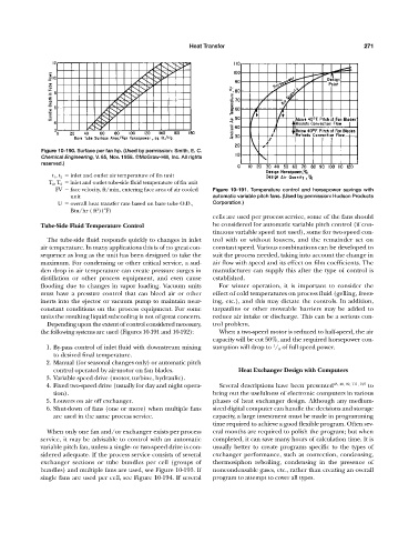
FV face velocity, ft/min, entering face area of air cooled Figure 10-191. Temperature control and horsepower savings with
unit automatic variable pitch fans. (Used by permission: Hudson Products
U overall heat transfer rate based on bare tube O.D., Corporation.)
2
Btu/hr ( ft )(°F)
cells are used per process service, some of the fans should
Tube-Side Fluid Temperature Control be considered for automatic variable pitch control (if con-
tinuous variable speed not used), some for two-speed con-
The tube-side fluid responds quickly to changes in inlet trol with or without louvers, and the remainder set on
air temperature. In many applications this is of no great con- constant speed. Various combinations can be developed to
sequence as long as the unit has been designed to take the suit the process needed, taking into account the change in
maximum. For condensing or other critical service, a sud- air flow with speed and its effect on film coefficients. The
den drop in air temperature can create pressure surges in manufacturer can supply this after the type of control is
distillation or other process equipment, and even cause established.
flooding due to changes in vapor loading. Vacuum units For winter operation, it is important to consider the
must have a pressure control that can bleed air or other effect of cold temperatures on process fluid (gelling, freez-
inerts into the ejector or vacuum pump to maintain near- ing, etc.), and this may dictate the controls. In addition,
constant conditions on the process equipment. For some tarpaulins or other moveable barriers may be added to
units the resulting liquid subcooling is not of great concern. reduce air intake or discharge. This can be a serious con-
Depending upon the extent of control considered necessary, trol problem.
the following systems are used (Figures 10-191 and 10-192): When a two-speed motor is reduced to half-speed, the air
capacity will be cut 50%, and the required horsepower con-
1
1. By-pass control of inlet fluid with downstream mixing sumption will drop to / 8 of full speed power.
to desired final temperature.
2. Manual (for seasonal changes only) or automatic pitch
control operated by air-motor on fan blades. Heat Exchanger Design with Computers
3. Variable speed drive (motor, turbine, hydraulic).
4. Fixed two-speed drive (usually for day and night opera- Several descriptions have been presented 43, 48, 92, 111, 125 to
tion). bring out the usefulness of electronic computers in various
5. Louvers on air off exchanger. phases of heat exchanger design. Although any medium-
6. Shut-down of fans (one or more) when multiple fans sized digital computer can handle the decisions and storage
are used in the same process service. capacity, a large investment must be made in programming
time required to achieve a good flexible program. Often sev-
When only one fan and/or exchanger exists per process eral months are required to polish the program; but when
service, it may be advisable to control with an automatic completed, it can save many hours of calculation time. It is
variable pitch fan, unless a single- or two-speed drive is con- usually better to create programs specific to the types of
sidered adequate. If the process service consists of several exchanger performance, such as convection, condensing,
exchanger sections or tube bundles per cell (groups of thermosiphon reboiling, condensing in the presence of
bundles) and multiple fans are used, see Figure 10-193. If noncondensable gases, etc., rather than creating an overall
single fans are used per cell, see Figure 10-194. If several program to attempt to cover all types.