
Page 310 - Applied Process Design For Chemical And Petrochemical Plants Volume III
P. 310
66131_Ludwig_CH10G 5/30/2001 4:41 PM Page 269
Heat Transfer 269
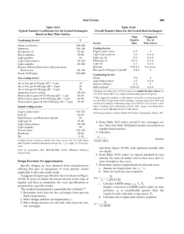
Table 10-51 Table 10-52
Typical Transfer Coefficients for Air-Cooled Exchangers Overall Transfer Rates for Air-Cooled Heat Exchangers
Based on Bare Tube Surface
*Stab **Suggested
Condensing Service U Transfer No. of
Service Rate Tube Layers
Amine reactivator 100—120
Ammonia 105—125 Cooling Service
Refrigerant 12 75—90 Engine jacket water 0.6—7 4
Heavy naphtha 70—90 Light hydrocarbons 0.4—5 4 or 6
Light gasoline 95 Light gas oil 0.3—4 4 or 6
Light hydrocarbons 095—105 Heavy gas oil 2.5—3 4 or 6
Light naphtha 080—100 Lube oil 0.1—2 4 or 6
Reactor effluent Platformers, Hydroformers, Bottoms .0.75—1.5 6 or more
Rexformers 080—100 Flue gas @ 100 psig & 5 psi P 00..2—2.5 4
Steam (0—20 psig) 135—200
Condensing Service
Gas cooling service Steam 0.7—8 4
Light hydrocarbon 0.4—5 4 or 6
Air or flue gas @ 50 psig ( P 1 psi) 10 Reactor effluent 0.3—4 6
Air or flue gas @ 100 psig ( P 2 psi) 20 Still overhead .2.75—3.5 4 or 6
Air or flue gas @ 100 psig ( P 5 psi) 30
2
*Transfer rate, Btu/(hr) (ft )(°F), based on outside fin tube surface for
Ammonia reactor stream 090—110
1-in. O.D. tubes with / 8 in. high aluminum fins spaced 11 per in.
5
Hydrocarbon gasses @ 15—50 psig ( P 1 psi) 30—40
Hydrocarbon gasses @ 50—250 psig ( P 3 psi) 50—60 **The suggested number of tube layers cannot be accurately predicted
for all services. In general coolers having a cooling range up to 80°F and
Hydrocarbon gasses @ 250—1500 psig ( P 5 psi) 70—90
condensers having a condensing range up to 50°F are selected with 4 tube
Liquid cooling service layers. Cooling and condensing services with ranges exceeding these
values are generally figured with 6 tube layers.
Engine jacket water 130—155
Used by permission: Griscom-Russell/Ecolaire Corporation, Easton, PA.
Fuel oil 20—30
Hydroformer and Platformer liquids 85
Light gas oil 70—90
4. From Table 10-51 select overall U for exchanger ser-
Light hydrocarbons 090—120
vice. Note that Table 10-52 gives transfer rates based on
Light naphtha 90
outside finned surface.
Process water 120—145
5. Calculate,
Residuum 10—20
Tar 05—10
T 1 t 1
(10-304)
Coefficients are based on outside bare tube surface for 1-in. O.D. tubes U1bare tube2
with 10 plain extruded aluminum fins per in., / 8 in. high, 21.2:1 surface
5
ratio.
and from Figure 10-188, read optimum bundle tube
Used by permission: Bul. M92-300-3MC 10/94. ©Hudson Products row depth.
Corporation.
6. From Table 10-53, select (a) typical standard air face
velocity, (b) ratio of surface area to face area, and (c)
Design Procedure for Approximation ratio of weight to face area.
Specific designs are best obtained from manufacturers 7. Determine surface requirements by trial and error:
offering this type of equipment or from specific curves a. Assume air temperature rise, t 2 t 1 .
applicable to the units under study. b. Solve for total face area required:
A suggested inquiry specification sheet is shown in Figure Q
FA (10-305)
10-186. It serves to define the known factors at the time of 1t 2 t 1 21FV211.082
inquiry and then to summarize the exact specifications as
c. Calculate LMTD using t 1 , t 2 , T 1 , T 2
proposed by a specific vendor. Neglect correction to LMTD unless outlet air tem-
The method summarized is essentially that of Smith. 106
perature, t 2 , is considerably greater than the
1. Determine heat duty for the exchanger from process
required outlet tube-side temperature, T 2 .
fluid temperatures.
d. Calculate bare or plain tube surface required:
2. Select design ambient air temperature, t 1 .
3. Select design pressure on tube side, tube material, tube Q
A
size, and gage. U1LMTD2