Page 311 - Applied Process Design For Chemical And Petrochemical Plants Volume III
P. 311

66131_Ludwig_CH10G  5/30/2001 4:41 PM  Page 270


                       270                       Applied Process Design for Chemical and Petrochemical Plants

                                           Table 10-53
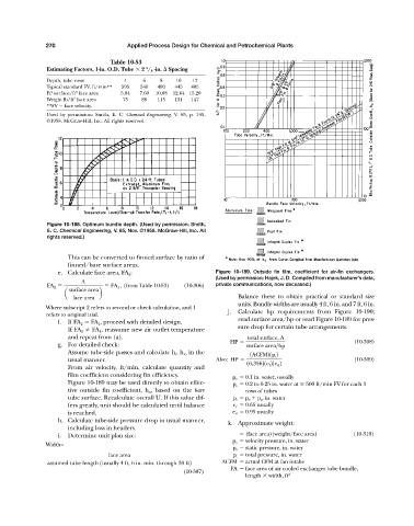
                       Estimating Factors, 1-in. O.D. Tube   2  / 8 -in.   Spacing
                                                       3
                       Depth, tube rows         4     6    8    10    12
                       Typical standard FV, ft/min**  595  540  490  445  405
                         2
                                 2
                       Ft surface/ft face area  5.04  7.60  10.08  12.64 15.20
                                2
                       Weight lb/ft face area  75    88   115   131  147
                       **FV   face velocity.
                       Used by permission: Smith, E. C.  Chemical Engineering, V. 65, p. 145,
                       ©1958. McGraw-Hill, Inc. All rights reserved.


                       Figure 10-188. Optimum bundle depth. (Used by permission: Smith,
                       E. C. Chemical Engineering, V. 65, Nov. ©1958. McGraw-Hill, Inc. All
                       rights reserved.)


                              This can be converted to finned surface by ratio of
                              finned/bare surface areas.
                           e. Calculate face area, FA 2 :                    Figure 10-189.  Outside fin film, coefficient for air-fin exchangers.
                                                                             (Used by permission: Hajek, J. D. Compiled from manufacturer’s data,
                                  A
                       FA 2                 FA 1   , (from Table 10-53)  (10-306)  private communications, now deceased.)
                              surface area
                             a          b
                                face area                                           Balance these to obtain practical or standard size
                                                                                    units. Bundle widths are usually 4 ft, 6 in. and 7 ft, 6 in.
                       Where subscript 2 refers to second or check calculation, and 1
                                                                                 j.  Calculate hp requirements from Figure 10-190;
                       refers to original trial.
                                                                                    read surface area/hp or read Figure 10-189 for pres-
                           f.  If FA 2   FA 1 , proceed with detailed design.
                                                                                    sure drop for certain tube arrangements.
                              If FA 2   FA 1 , reassume new air outlet temperature
                              and repeat from (a).                                     total surface, A
                                                                                 HP                                      (10-308)
                           g. For detailed check:                                      surface area>hp
                              Assume tube-side passes and calculate h i , h io in the   1ACFM21p t 2
                              usual manner.                                  Also: HP                                    (10-309)
                                                                                       16,35621e f 21e d 2
                              From air velocity, ft/min, calculate quantity and
                              film coefficient considering fin efficiency.        p v   0.1 in. water, usually
                              Figure 10-189 may be used directly to obtain effec-  p s   0.2 to 0.25 in. water at   500 ft/min FV for each 3
                              tive outside fin coefficient, h o , based on the  bare  rows of tubes
                              tube surface. Recalculate overall U. If this value dif-  p t   p v 	 p s , in. water
                              fers greatly, unit should be calculated until balance  e r   0.65 usually
                              is reached.                                         e d   0.95 usually
                           h. Calculate tube-side pressure drop in usual manner,
                                                                                 k. Approximate weight:
                              including loss in headers.
                           i.  Determine unit plan size:                              (face area)(weight/face area)      (10-310)
                                                                                  p v   velocity pressure, in. water
                       Width=
                                                                                  p s   static pressure, in. water
                                           face area                              p t   total pressure, in. water
                       assumed tube length 1usually 4 ft, 6 in. min. through 30 ft2  ACFM   actual CFM at fan intake
                                                                                  FA   face area of air cooled exchanger tube bundle,
                                                                   (10-307)
                                                                                      length   width, ft 2
   306   307   308   309   310   311   312   313   314   315   316