
Page 80 - Applied Process Design For Chemical And Petrochemical Plants Volume III
P. 80
66131_Ludwig_CH10B 5/30/2001 4:18 PM Page 58
58 Applied Process Design for Chemical and Petrochemical Plants
T Log Mean Temperature difference LMTD actual flow paths and accompanying temperature devia-
here: t 1 Temperature difference at one end of exchanger tions.
(smaller value), see Figure 10-29. Note that where Figures 10-34A—J represent corrections to
t 2 Temperature difference at other end of exchanger the LMTD for the physical configuration of the exchanger,
(larger value) Figures 10-35A—C represent the temperature efficiency of
ln Natural logarithm to base e
the unit and are not the same as the LMTD correction.
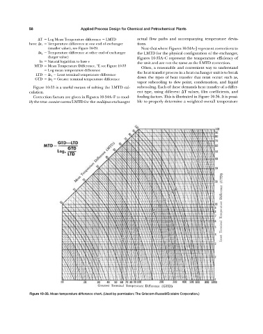
MTD Mean Temperature Difference, °F, see Figure 10-33
Often, a reasonable and convenient way to understand
Log mean temperature difference
the heat transfer process in a heat exchanger unit is to break
LTD t 1 Least terminal temperature difference
down the types of heat transfer that must occur: such as,
GTD t 2 Greater terminal temperature difference
vapor subcooling to dew point, condensation, and liquid
Figure 10-33 is a useful means of solving the LMTD cal- subcooling. Each of these demands heat transfer of a differ-
culation. ent type, using different T values, film coefficients, and
Correction factors are given in Figures 10-34A—F to mod- fouling factors. This is illustrated in Figure 10-36. It is possi-
ify the true counter-current LMTD for the multipass exchanger ble to properly determine a weighted overall temperature
Figure 10-33. Mean temperature difference chart. (Used by permission: The Griscom-Russell/Ecolaire Corporation.)