
Page 78 - Applied Process Design For Chemical And Petrochemical Plants Volume III
P. 78
66131_Ludwig_CH10B 5/30/2001 4:17 PM Page 56
56 Applied Process Design for Chemical and Petrochemical Plants
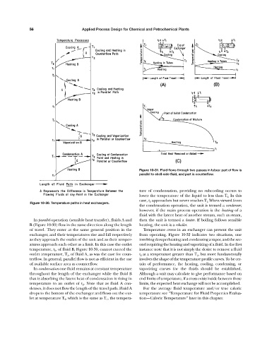
Figure 10-31. Fluid flows through two passes in tubes: part of flow is
parallel to shell-side fluid, and part is counterflow.
ture of condensation, providing no subcooling occurs to
lower the temperature of the liquid to less than T 2. In this
case, t 2 approaches but never reaches T 2. When viewed from
Figure 10-30. Temperature paths in heat exchangers.
the condensation operation, the unit is termed a condenser;
however, if the main process operation is the heating of a
fluid with the latent heat of another stream, such as steam,
In parallel operation (sensible heat transfer), fluids A and then the unit is termed a heater. If boiling follows sensible
B (Figure 10-30) flow in the same direction along the length heating, the unit is a reboiler.
of travel. They enter at the same general position in the Temperature crosses in an exchanger can prevent the unit
exchanger, and their temperatures rise and fall respectively from operating. Figure 10-32 indicates two situations, one
as they approach the outlet of the unit and as their temper- involving desuperheating and condensing a vapor, and the sec-
atures approach each other as a limit. In this case the outlet ond requiring the heating and vaporizing of a fluid. In the first
temperature, t 2 , of fluid B, Figure 10-30, cannot exceed the instance note that it is not simply the desire to remove a fluid
outlet temperature, T 2 , of fluid A, as was the case for coun- t 2 at a temperature greater than T 2 , but more fundamentally
terflow. In general, parallel flow is not as efficient in the use involves the shape of the temperature profile curves. To be cer-
of available surface area as counterflow. tain of performance, the heating, cooling, condensing, or
In condensation one fluid remains at constant temperature vaporizing curves for the fluids should be established.
throughout the length of the exchanger while the fluid B Although a unit may calculate to give performance based on
that is absorbing the latent heat of condensation is rising in end limits of temperature, if a cross exists inside between these
temperature to an outlet of t 2 . Note that as fluid A con- limits, the expected heat exchange will not be accomplished.
denses, it does not flow the length of the travel path. Fluid A For the average fluid temperature and/or true caloric
drops to the bottom of the exchanger and flows out the out- temperature see “Temperature for Fluid Properties Evalua-
let at temperature T 2 , which is the same as T 1 , the tempera- tion—Caloric Temperature” later in this chapter.