
Page 77 - Applied Process Design For Chemical And Petrochemical Plants Volume III
P. 77
66131_Ludwig_CH10B 5/30/2001 4:17 PM Page 55
Heat Transfer 55
Note that the logarithmic mean temperature difference
should be used when the following conditions generally
apply 107 for conditions of true counter-current or co-current
flow:
• Constant overall heat transfer coefficient.
• Complete mixing within any shell cross pass or tube
pass.
• The number of cross baffles is large (more than 4).
• Constant flow rate and specific.
• Enthalpy is a linear function of temperature.
• Equal surfaces in each shell pass or tube pass.
• Negligible heat loss to surroundings or internally
between passes.
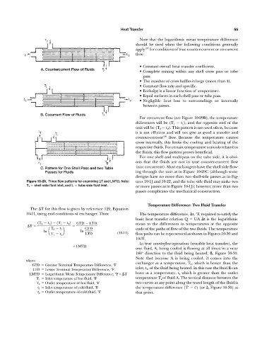
For co-current flow (see Figure 10-29B), the temperature
differences will be (T 1 t 1 ), and the opposite end of the
unit will be (T 2 t 2 ). This pattern is not used often, because
it is not efficient and will not give as good a transfer and
counter-current 129 flow. Because the temperature cannot
cross internally, this limits the cooling and heating of the
respective fluids. For certain temperature controls related to
the fluids, this flow pattern proves beneficial.
For one shell and multipass on the tube side, it is obvi-
ous that the fluids are not in true counter-current flow
(nor co-current). Most exchangers have the shell side flow-
ing through the unit as in Figure 10-29C (although some
designs have no more than two shell-side passes as in Fig-
Figure 10-29. Three flow patterns for examining T and LMTD. Note: ures 10-1J and 10-22, and the tube side fluid may make two
T 1 shell-side fluid inlet, and t 1 tube-side fluid inlet. or more passes as in Figure 10-1J); however, more than two
passes complicates the mechanical construction.
Temperature Difference: Two Fluid Transfer
The T for this flow is given by reference 129, Equation
10-11, using end conditions of exchanger. Thus: The temperature difference, t, °F, required to satisfy the
basic heat transfer relation Q UA t is the logarithmic
1T 2 t 1 2 1T 1 t 2 2 GTD LTD mean to the differences in temperatures at the opposite
T
T 2 t 1 GTD ends of the paths of flow of the two fluids. The temperature
ln a b ln
LTD (10-11) flow paths can be represented as shown in Figures 10-30 and
T 1 t 2
10-31.
In true counterflow operation (sensible heat transfer), the
= LMTD
one fluid, A, being cooled is flowing at all times in a near
180° direction to the fluid being heated, B, Figure 10-30.
Note that because A is being cooled, it comes into the
where
GTD Greater Terminal Temperature Difference, °F exchanger at a temperature, T 1 , which is hotter than the
LTD Lesser Terminal Temperature Difference, °F inlet, t 1 , of the fluid being heated. In this case the fluid B can
LMTD Logarithmic Mean Temperature Difference, °F = T leave at a temperature, t 2 which is greater than the outlet
T 1 Inlet temperature of hot fluid, °F temperature T 2 of fluid A. The vertical distance between the
T 2 Outlet temperature of hot fluid, °F two curves at any point along the travel length of the fluid is
t 1 Inlet temperature of cold fluid, °F the temperature difference (T' t') (or , Figure 10-30) at
t 2 Outlet temperature of cold fluid, °F that point.