
Page 72 - Applied Process Design For Chemical And Petrochemical Plants Volume III
P. 72
66131_Ludwig_CH10B 5/30/2001 4:17 PM Page 51
Heat Transfer 51
Effective Tube Surface 1-in. O.D. tubes. The accuracy of extrapolation to other
diameters has not been determined. The chart is applicable
The effective tube surface is usually evaluated on the out- to low-finned tubes, as well as to plain tubes. However, it is
side tube surface. Use net tube length. restricted to either two- or four-tube passes. For arrange-
Net effective outside area for plain or bare tubes is: ments other than those used in the chart preparation, the
chart may be used at the designer’s discretion. As an exam-
2
A n = (ft external surface per ft length from Table 10-3) (L e , ple of those “beyond limits,” the following is a comparison of
net effective tube length) (N t , number of tubes) (10-4)
calculated areas with actual areas for various U-tube bundles
installed in a chemical plant:
Net effective outside area for finned tube is:
No. of Inside Calc’d*
2
A nf = (ft external finned surface per ft length from U- Tube Tube Area Act. %
Table 10-39 or other specific tube data) (L e , net Tubes Tube Size Pitch R.O.B. Ft 2 Area Error
effective tube length) (N t , number of tubes) (10-5)
66 3 / 4 in. O.D. 32 ft 1 in. 2 in. 400.0 405.7 1.43
88 3 / 4 in. O.D. 32 ft 1 in. 2 in. 534 533 0.19
Effective Tube Length for U-Tube Heat Exchangers
1
54 1 in. O.D. 32 ft 1 / 4 in. 3 in. 439 448 2.05
One challenge in the design of U-tube heat exchangers is Note: R.O.B. Radius of bend.
to determine the effective length of the tubes. For example, *The calculated areas were based on Figure 10-27B using only the
when U-tube bundles are fabricated from 12-ft tubes, the respective tube size and number of tubes.
maximum length tube in the bundle is 12 ft which is in the
outside tube row. The inside tube is the shortest and is less
than 12 ft long. Example 10-2. Use of U-Tube Area Chart 124
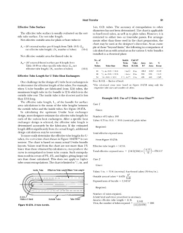
The effective tube length, L e , of the bundle for surface
Case 1
area calculations is the mean of the tube lengths between
the outside tubes and the inside tubes. See Figure 10-27A.
Given:
In calculating the optimum U-tube heat exchanger
design, most designers estimate the effective tube length for Number of U-tubes: 168
each of the various heat exchangers. After a specific heat
Tubes: 0.75 in. O.D. 16 ft (nominal) plain tubes
exchanger design is selected, the effective tube length is
determined accurately by the fabricator. If the estimated
Required:
length differs significantly from the actual length, additional
design calculations may be necessary. Total effective exposed area.
To more easily determine the effective tube lengths for U-
tubes, the correction chart shown in Figure 10-27B 124 is con- From Figure 10-27B:
venient. The chart is based on many actual U-tube bundle
layouts. Values read from the chart are not more than 1% Effective tube length 14.5 ft.
lower than those obtained by calculations, except where the 0.75
Total effective exposed area 114.5211682 a b = 478.3 ft 2
curve is extrapolated to lower tube counts. Such extrapola- 12
tions result in errors of 3%, 4%, and higher, giving larger val-
ues than those calculated. This does not apply to higher Case 2
3
tube count extrapolations. The chart is limited to / 4 -in. and
Given:
Tubes: 1 in. 12 ft (nominal) low-finned tubes (19 fins/in.).
ft 2
Outside area of tubes 0.678
linft
Exposed area of bundle 2,142 ft 2
Required:
Number of tubes required.
A brief trial and error procedure is necessary.
Assume effective tube length 11 ft. 2,142
Thus, the number of tubes required 288
Figure 10-27A. U-tube bundle. 1112 10.6782