Page 71 - Applied Process Design For Chemical And Petrochemical Plants Volume III
P. 71

66131_Ludwig_CH10B  5/30/2001 4:17 PM  Page 50


                       50                        Applied Process Design for Chemical and Petrochemical Plants

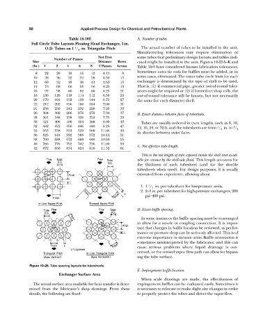
                                           Table 10-10E                      A. Number of tubes.
                        Full Circle Tube Layouts Floating Head Exchanger, 1-in.
                                              1
                               O.D. Tubes on 1  / 4 -in. Triangular Pitch      The actual number of tubes to be installed in the unit.
                                                                             Manufacturing tolerances may require elimination of
                                                          Net Free           some tubes that preliminary design layouts and tables indi-
                                   Number of Passes
                         Size                             Distance  Rows     cated might be installed in the unit. Figures 10-25A—K and
                         (In.)  1   2     4     6     8   2 Passes  Across   Table 10-9 have considered known fabrication tolerances.
                                                                             Sometimes extra tie rods for baffles must be added, or in
                          8    22    20    18   16    12    4.13     9
                                                                             some cases, eliminated. The outer tube circle limit for each
                         10    38    36    32   32    28    4.50     13
                         12    60    52    48   46    44    4.63     15      exchanger is determined by the type of shell to be used.
                         14    73    68    60   58    56    4.25     19      That is, (1) if commercial pipe, greater out-of-round toler-
                         16    97    98    86   82    80    4.25     21      ances might be required or (2) if formed on shop rolls, the
                         18   130   126   118  114   112    6.50     25      out-of-round tolerance will be known, but not necessarily
                         20   170   164   152  150   144    6.75     27      the same for each diameter shell.
                         22   212   202   196  188   184    7.00     31
                         24   258   250   242  232   228    7.25     33
                         26   304   302   286  278   272    7.50     37      B. Exact distance between faces of tubesheets.
                         28   361   348   338  336   324    7.75     39
                         30   421   408   400  394   388    8.00     43        Tubes are usually ordered in even lengths, such as 8, 10,
                         32   482   472   456  446   440    8.25     47                                              1       1
                                                                             12, 16, 24, or 32 ft, and the tubesheets are from  / 4 in. to  / 2
                         34   555   538   524  520   500   11.06     49
                                                                             in. shorter between outer faces.
                         36   625   618   592  588   572   10.44     51
                         38   700   688   672  660   640   10.69     55
                         40   786   776   752  742   736   11.00     59
                                                                             C. Net effective tube length.
                         42   872   850   834  824   816   11.32     61
                                                                               This is the net length of tube exposed inside the shell and avail-
                                                                             able for contact by the shell-side fluid. This length accounts for
                                                                             the thickness of each tubesheet (and for the double
                                                                             tubesheets when used). For design purposes, it is usually
                                                                             estimated from experience, allowing about


                                                                                   1
                                                                               1. 1  / 2 in. per tubesheet for low-pressure units.
                                                                               2. 2—3 in. per tubesheet for high-pressure exchangers, 200
                                                                                 psi—400 psi.


                                                                             D. Exact baffle spacing.

                                                                               In some instances the baffle spacing must be rearranged
                                                                             to allow for a nozzle or coupling connection. It is impor-
                                                                             tant that changes in baffle location be reviewed, as perfor-
                                                                             mance or pressure drop can be seriously affected. This is of
                                                                             extreme importance in vacuum units. Baffle orientation is
                                                                             sometimes misinterpreted by the fabricator, and this can
                                                                             cause serious problems where liquid drainage is con-
                                                                             cerned, or the revised vapor flow path can allow for bypass-
                                                                             ing the tube surface.

                       Figure 10-26. Tube spacing layouts for tubesheets.
                                                                             E. Impingement baffle location.
                                      Exchanger Surface Area
                                                                               When scale drawings are made, the effectiveness of
                         The actual surface area available for heat transfer is deter-  impingement baffles can be evaluated easily. Sometimes it
                       mined from the fabricator’s shop drawings. From these  is necessary to relocate or make slight size changes in order
                       details, the following are fixed:                     to properly protect the tubes and direct the vapor flow.
   66   67   68   69   70   71   72   73   74   75   76