
Page 239 -
P. 239
Gas and Liquid Injection Rates 201
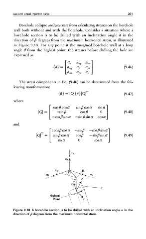
Borehole collapse analyses start from calculating stresses on the borehole
wall both without and with the borehole. Consider a situation where a
borehole section is to be drilled with an inclination angle α in the
direction of β degrees from the maximum horizontal stress, as illustrated
in Figure 9.18. For any point at the imagined borehole wall at a loop
angle θ from the highest point, the stresses before drilling the hole are
expressed as
2 3
σ x σ xy σ xz
^ σ fg = 4 σ xy σ y σ yz 5 (9.46)
σ xz σ yz σ z
The stress components in Eq. (9.46) can be determined from the fol-
lowing transformation:
T
f^σg = ½Qfσg½Q (9.47)
where
cos β cos α sin β cos α sin α
2 3
½Q = 4 −sin β cos β 0 5 (9.48)
−cos β sin α −sin β sin α cos α
and
c cos β cos α −sin β −cos β sin α
2 3
½Q = 4 sin β cos α cos β −sin β sin α 5 (9.49)
T
sin α 0 cos α
σ v
z 0
x 0 y 0
σ H β σ h
α y
z
θ
Highest
Point x
Figure 9.18 A borehole section is to be drilled with an inclination angle α in the
direction of β degrees from the maximum horizontal stress.