
Page 246 -
P. 246
208 Part III Underbalanced Drilling Systems
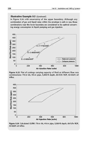
Illustrative Example 9.5 (Continued )
in Figure 9.24 with uncertainty of the upper boundary. Although any
combination of gas and liquid rates within the envelope is safe to use, those
combinations near the lower boundary are considered to be optimal concern-
ing energy consumption in liquid pumping and gas injection.
450
400
Mud Flow Rate (gpm) 300 E = 3.46 lbf-ft/ft 3 3
350
E = 7.77 lbf-ft/ft
250
200
150
100
E = 0.86 lbf-ft/ft 3 Balanced pressure
50
Collapse pressure
0
0 200 400 600 800 1000
Air Injection Rate (scfm)
Figure 9.23 Plot of cuttings carrying capacity of fluid at different flow rate
combinations: 7⅞-in bit, 4½-in pipe, 5,000-ft depth, 60-ft/hr ROP, 42-bbl/h oil
influx.
450
400
Mud Flow Rate (gpm) 300
350
250
200
150
100
50
0
0 200 400 600 800 1000
Air Injection Rate (scfm)
Figure 9.24 Calculated GLRW: 7⅞-in bit, 4½-in pipe, 5,000-ft depth, 60-ft/hr ROP,
42-bbl/h oil influx.