
Page 120 - Applied Petroleum Geomechanics
P. 120
112 Applied Petroleum Geomechanics
(A) (B)
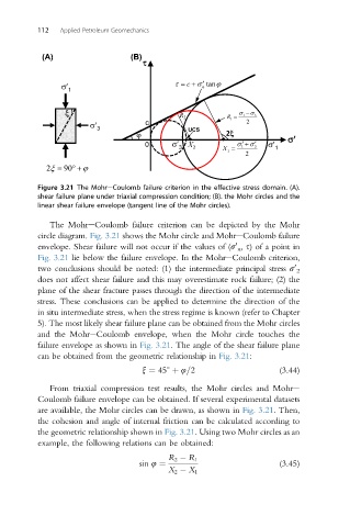
Figure 3.21 The MohreCoulomb failure criterion in the effective stress domain. (A).
shear failure plane under triaxial compression condition; (B). the Mohr circles and the
linear shear failure envelope (tangent line of the Mohr circles).
The MohreCoulomb failure criterion can be depicted by the Mohr
circle diagram. Fig. 3.21 shows the Mohr circle and MohreCoulomb failure
envelope. Shear failure will not occur if the values of (s n , s) of a point in
0
Fig. 3.21 lie below the failure envelope. In the MohreCoulomb criterion,
0
two conclusions should be noted: (1) the intermediate principal stress s 2
does not affect shear failure and this may overestimate rock failure; (2) the
plane of the shear fracture passes through the direction of the intermediate
stress. These conclusions can be applied to determine the direction of the
in situ intermediate stress, when the stress regime is known (refer to Chapter
5). The most likely shear failure plane can be obtained from the Mohr circles
and the MohreCoulomb envelope, when the Mohr circle touches the
failure envelope as shown in Fig. 3.21. The angle of the shear failure plane
can be obtained from the geometric relationship in Fig. 3.21:
x ¼ 45 þ 4=2 (3.44)
From triaxial compression test results, the Mohr circles and Mohre
Coulomb failure envelope can be obtained. If several experimental datasets
are available, the Mohr circles can be drawn, as shown in Fig. 3.21. Then,
the cohesion and angle of internal friction can be calculated according to
the geometric relationship shown in Fig. 3.21. Using two Mohr circles as an
example, the following relations can be obtained:
R 2 R 1
sin 4 ¼ (3.45)
X 2 X 1