
Page 199 - Applied Petroleum Geomechanics
P. 199
194 Applied Petroleum Geomechanics
DFIT, mini-frac and wireline tests, or LWD micro-frac tests (Ramakrishnan
et al., 2009). In a hydraulic fracture test, an interval of borehole is isolated and
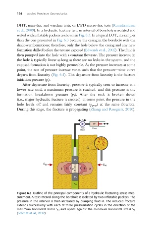
sealed with inflatable packers as shown in Fig. 6.3. In a typical LOT, it is simpler
than the one presented in Fig. 6.3 because the casing in the borehole seals the
shallower formations; therefore, only the hole below the casing and any new
formation drilled before the test are exposed (Edwardsetal.,2002). The fluid is
then pumped into the hole with a constant flowrate. The pressure increase in
the hole is typically linear as long as there are no leaks in the system, and the
exposed formation is not highly permeable. As the pressure increases at some
point, the rate of pressure increase varies such that the pressureetime curve
departs from linearity (Fig. 6.4). This departure from linearity is the fracture
initiation pressure (p i ).
After departure from linearity, pressure is typically seen to increase at a
lower rate until a maximum pressure is reached, and this pressure is the
formation breakdown pressure (p b ). After the rock is broken down
(i.e., major hydraulic fracture is created), at some point the pressure in the
hole levels off and remains fairly constant (p prop ) at the same flowrate.
During this stage, the fracture is propagating (Zhang and Roegiers, 2010).
Figure 6.3 Outline of the principal components of a hydraulic fracturing stress mea-
surement. A test interval along the borehole is isolated by two inflatable packers. The
pressure in the interval is then increased by pumping fluid in. The induced fracture
extends successively with each of three pressurization cycles in the direction of the
maximum horizontal stress S H and opens against the minimum horizontal stress S h
(Schmitt et al., 2012).