
Page 25 - Applied Petroleum Geomechanics
P. 25
Stresses and strains 15
deformation is allowed. In this case, the relationship of three principal
stresses can be obtained from Eq. (1.20) by substituting ε x ¼ ε y ¼ 0:
n
s x ¼ s y ¼ s z (1.21)
1 n
If s x , s y , and s z represent three in situ stresses in the subsurface, then the
in situ stresses in the uniaxial strain condition have the following relation:
n
s h ¼ s H ¼ s V (1.22)
1 n
where s h , s H , and s V are the minimum and maximum horizontal, and ver-
tical stresses, respectively.
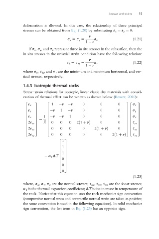
1.4.3 Isotropic thermal rocks
Stressestrain relations for isotropic, linear elastic dry materials with consid-
eration of thermal effect can be written as shown below (Bower, 2010):
2 3 2 32 3
ε x 1 n n 0 0 0 s x
ε
6 y 7 6 n 1 n 0 0 0 76 s y 7
7
6
6
76
7
6 7 6 76 7
6 ε z 7 1 6 n n 1 0 0 0 76 s z 7
6 7 ¼ 6 76 7
E
6 7 6 0 0 0 2ð1 þ nÞ 0 0 76 s 7
6 2ε yz 7 6 76 yz 7
6 7 6 76 7
4 2ε xz 5 4 0 0 0 0 2ð1 þ nÞ 0 54 s xz 5
2ε xy 0 0 0 0 0 2ð1 þ nÞ s xy
1
2 3
1
6 7
6 7
6 7
a T DT 6 1 7
6 7
0
6 7
6 7
6 7
4 0 5
0
(1.23)
where, s x , s y , s z are the normal stresses; s xy , s yz , s xz are the shear stresses;
a T is the thermal expansion coefficient; DT is the increase in temperature of
the rock. Notice that this equation uses the rock mechanics sign convention
(compressive normal stress and contractile normal strain are taken as positive;
the same convention is used in the following equations). In solid mechanics
sign convention, the last term in Eq. (1.23) has an opposite sign.