
Page 101 - Applied Photovoltaics
P. 101
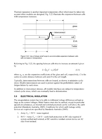
Thermal expansion is another important temperature effect which must be taken into
                     account when modules are designed. Fig. 5.22 illustrates the expansion between cells
                     with temperature increases.
                                                        C


                                                                                glass


                                                              interconnect

                                                                              cell
                                                                                EVA


                                                                               Tedlar

                                           D

                            Figure 5.22. Use of stress relief loops to accommodate expansion between cells
                            with increases in temperature.

                     Referring to Fig. 5.22, the spacing between cells tries to increase an amount į given
                     by
                                                 į      CĮ    Į  D   Tǻ            (5.3)
                                                      g     c
                     where Į g , Į c  are the expansion coefficients of the glass and cell, respectively, C is the
                     centre-to-centre distance between cells and D is the cell length.
                     Typically, interconnections between cells are looped, as shown, to minimise cyclic
                     stress. Double interconnects are used to protect against the probabilistic nature of
                     fatigue failure by such stress.
                     In addition to interconnect stresses, all module interfaces are subject to temperature-
                     related cyclic stress, which can eventually lead to delamination.

                     5.9    ELECTRICAL    INSULATION
                     The encapsulation system has to be able to withstand voltage differences at least as
                     large as the system voltages. Metal frames must also be earthed, except in particular
                     special circumstances, as internal and terminal potentials can be well above the earth
                     potential (Standards Australia, 2005). Conditions for which earth leakage safety
                     devices are required are specified by Standards Australia (2005):
                         1. Array V oc  < 50 V—none required.

                         2. 50 V < Array V oc  < 120 V—earth fault protection on DC side required if
                            system earthed and isolated, or DC-sensitive residual current device on AC
                            side if not isolated.


                     88