
Page 103 - Applied Photovoltaics
P. 103
expected to fail or to degrade in a number of ways, with long term performance
studies indicating typical losses in the range 1–2% per year (King et al., 2000). Ross
(1980) gives expected reduction in output due to various degradation modes for each
year of operation:
1. Front surface soiling—Module performance can be reduced by the
accumulation of dirt on the top surface. Self cleaning of glass-surfaced
modules by wind and rain keeps these losses under 10%; however they can be
much more significant for other surface materials.
2. Cell degradation—A gradual degradation in module performance can be
caused by:
x increases in R s owing to decreased adherence of contacts or corrosion
x decreases in R sh owing to metal migration through the p-n junction
x antireflection coating deterioration
x degradation of the cell active p-type material by the interaction of boron-
oxygen complexes (Schmidt & Cuevas, 1999).
3. Module optical degradation—Discolouration of the encapsulating materials
can result in a gradual drop in performance (Czanderna & Pern, 1996).
Yellowing can occur uniformly, because of UV exposure, temperature or
humidity, or locally, because of the diffusion of foreign matter from the edge
seals, mountings or terminal boxes of the module.
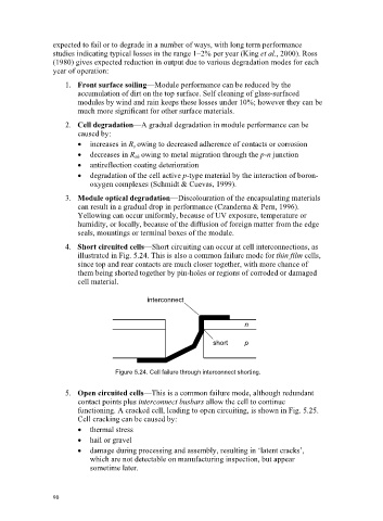
4. Short circuited cells—Short circuiting can occur at cell interconnections, as
illustrated in Fig. 5.24. This is also a common failure mode for thin film cells,
since top and rear contacts are much closer together, with more chance of
them being shorted together by pin-holes or regions of corroded or damaged
cell material.
interconnect
n
short p
Figure 5.24. Cell failure through interconnect shorting.
5. Open circuited cells—This is a common failure mode, although redundant
contact points plus interconnect busbars allow the cell to continue
functioning. A cracked cell, leading to open circuiting, is shown in Fig. 5.25.
Cell cracking can be caused by:
x thermal stress
x hail or gravel
x damage during processing and assembly, resulting in ‘latent cracks’,
which are not detectable on manufacturing inspection, but appear
sometime later.
90