
Page 16 - APPLIED PROCESS DESIGN FOR CHEMICAL AND PETROCHEMICAL PLANTS, Volume 1, 3rd Edition
P. 16
Process Planning, Scheduling and Flowsheet Design 5
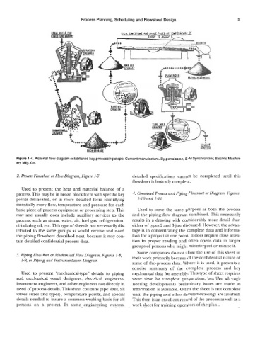
Figure 1-4. Pictorial flow diagram establishes key processing steps: Cement manufacture. By permission, E-M Synchronizer, Electric Machin-
ery Mfg. Co.
2. Process Flowsheet or Flow Diagram, Figure 1-7 detailed specifications cannot be completed until this
flowsheet is basically complete.
Used to present the heat and material balance of a
process. This may be in broad block form with specific key 4. Combined Process and piping Flowsheet or Diagram, Figures
points delineated, or in more detailed form identifylng 1-1 0 and 1-1 1
essentially every flow, temperature and pressure for each
basic piece of process equipment or processing step. This Used to serve the same purpose as both the process
may and usually does include auxiliary services to the and the piping flow diagram combined. This necessarily
process, such as steam, water, air, fuel gas, refrigeration, results in a drawing with considerably more detail than
circulating oil, etc. This type of sheet is not necessarily dis- either of types 2 and 3 just discussed. However, the advan-
tributed to the same groups as would receive and need tage is in concentrating the complete data and informa-
the piping flowsheet described next, because it may con- tion for a project at one point. It does require close atten-
tain detailed confidential process data. tion in proper reading and often opens data to larger
groups of persons who might misinterpret or misuse it.
Some companies do not allow the use of this sheet in
3. Piping Flowsheet or Mechanical Flow Diagram, Figures 1-8, their work primarily because of the confidential nature of
1-9, or Piping and Instrumentation Diagram
some of the.process data. Where it is used, it presents a
concise summary of the complete process and key
Used to present “mechanical-type’’ details to piping mechanical data for assembly. This type of sheet requires
and mechanical vessel designers, electrical engineers, more time for complete preparation, but like all engi-
instrument engineers, and other engineers not directly in neering developments preliminary issues are made as
need of process details. This sheet contains pipe sizes, all information is available. Often the sheet is not complete
valves (sizes and types), temperature points, and special until the piping and other detailed drawings are finished.
details needed to insure a common working basis for all This then is an excellent record of the process as well as a
persons on a project. In some engineering systems, work sheet for training operators of the plant.